Download
1 / 26
320 likes | 780 Views
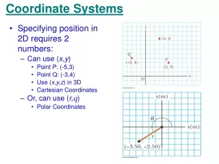
Coordinate Measuring Machine. Teacher : Ru-Li Lin Students : 49912049 Deng- Jhong Wang 49912069 Tsai-Feng Chiang Southern Taiwan University of Science and Technology. Outlines. History The Differences of 2D And 3D CMM Measurement Plan

E N D
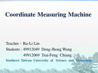
Coordinate Measuring Machine Teacher : Ru-Li Lin Students : 49912049 Deng-Jhong Wang 49912069 Tsai-Feng Chiang Southern Taiwan University of Science and Technology
Outlines • History • The Differences of 2D And 3D CMM • Measurement Plan • Contact probe measurement method Probe types • Non- Contact Measuring Machine NCMM probe types Pets Articulated Name of parts Applicable industries • Video • Conclusions
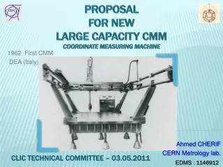
History Coordinate Measuring Mitutoyo Japan in 1968 the company launched, then in 1971 the British Rolls ‧ Royce has introduced a full range of touch probes, and gradually developed into a digital Coordinate Measuring Machine.
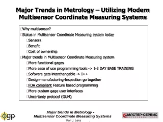
The Differences of 2D And 3D CMM • CNC Coordinate Measuring typically, the second element of manual measurements , the main difference of three million yuanmore than twice the Z-axis, suitable for a large number of identical three million artifacts , the advantage of high precision, but the machine is more expensive than the two million , is three to four times more thanthe second element.
Measurement Plan • First, develop the workpiece surface model for the reconstruction of the means, the coordinate measuring system settings, including the probe calibration, coordinate system settings and scanning parameters. • Then take measurements path planning, measurement results will be measured according to plan and get on the surface, the impact on the distribution of surface measurement data continuity is important.
Measurement System Settings And Plan • Work platform • Probe calibration • Coordinate System Settings • Auto scan parameter settings • Measurement area is divided • Select the scanning method • Scan Density decision
Contact probe measurement method • When using the touch probe surface measurements, select the methods have a great impact on the results. The measuring patterns can be divided into two kinds of triggers and continuous measurements.
Triggered measurements • General coordinate measuring instrument most commonly used .When generating signals trigger probe, the resistance of the coil will produce change, and sends a trigger signal , three-axis position detector signal is received, it will record position, but the disadvantage is slower.
Continuous measurement Continuous measurement commonly used in surface scanning, three-axis position variation generated by the contact sent to the controller uses the probe and the workpiece, so that the probe can be measured automatically scan the ups and downs alongthe surface.
probe types • Mechanical probe • Trigger probe
The Differences of Mechanical And Trigger • The main mechanical contact with the workpiece surface manually, use a foot switch to trigger signal is generated, the trigger is the center of the stylus from the original location to a specific angle, resulting detection signal measurements.
Ring bridge type • The most stable CMM-driven approach in the center of the table, you can reduce the impact caused by the bridge move.
Bridge type gantry Suitable for a large amount of volume and weight of the workpiece, and high-precision gears used in very large measure the workpiece, the aerospace industry, machine spindle.
Non- Contact Measuring Machine • NCMM with a laser scanner system is represented, compared to conventional touch probe, for complex workpiece measurement more easily , so the NCMM system users is increasing.
NCMM probe types Laser Displacement CCD type orientation
Pets Articulated Because of lightweight portable multi-joint,It can be installed in any location, coordinate measuring object contours traits scan. • Portability • Stable and reliable • Featured Measuring Hassle
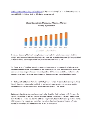
Applicable industries Widely used in vehicles and vehicle parts, molds, aerospace, shipbuilding, turbines and other machinery industry.
Video • ARCS 3D Coordinate Measurin https://www.youtube.com/watch?v=CEJJyPDIqCg • ROMER Articulated Arm PCMMs https://www.youtube.com/watch?v=SijGxj1CAs4 • BacesArm with ZEPHYR II http://www.youtube.com/watch?v=SK-mzm1_lC4
Conclusions • Because of the measurement functions in CMM, it made a very wide range of applications such as automotive, electronics, plastics and molds, etc.With the CMM, every industry has a close relationship to promote the development.CMM industry will gradually become an important instrument in the future,Simultaneously with the reverse engineering in enterprise development, it will also become an indispensable part.
Reference • http://www.pro-3d.com.tw/pviewitem1.asp?sn=697&area=&cat= • http://www2.ctu.edu.tw/98tew/98tew2-1/ • https://www.google.com.tw/search?q=%E6%9E%97%E5%AE%88%E5%84%80--%E4%B8%89%E6%AC%A1%E5%85%83%E7%B2%BE%E5%AF%86%E6%AA%A2%E6%B8%AC • http://www.baces3d.com/ • http://www.mitutoyo.com.tw/product/category.php?id=17