Download
1 / 15
150 likes | 282 Views
Laser surface coating of bulk metallic glass composition on high carbon low alloy steel. A. Basu 1* , J. Dutta Majumdar 2 , N.B. Dahotre 3 , I. Manna 2 1 Metallurgical & Materials Engineering Department, N.I.T., Rourkela Orissa. 769008

E N D
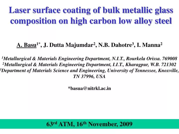
Laser surface coating of bulk metallic glass composition on high carbon low alloy steel A. Basu1*, J. Dutta Majumdar2, N.B. Dahotre3, I. Manna2 1Metallurgical & Materials Engineering Department, N.I.T., Rourkela Orissa. 769008 2Metallurgical & Materials Engineering Department, I.I.T., Kharagpur, W.B. 721302 3Department of Materials Science and Engineering, University of Tennessee, Knoxville, TN 37996, USA *basua@nitrkl.ac.in 63rd ATM, 16th November, 2009
Bulk Amorphous Alloy Met-glass is a supercooled liquid with no long-range periodicity and possessing near-theoretical strength, large elastic deformation, high hardness, excellent wear resistance [Klement, Willens, Duwez, Nature, 1960] • Properties of BAAs • Multi-component alloys • (dT/dt)Cr 103 K/s • Deep eutectic • -DHM (enthalpy of mixing) • h (viscosity) > 109 Pa-s at Tg • t (str. relax. time) near TMP Evolution of Met-glass/BAAs Klement et al., Nature (1960) Inoue et al., J. Mater. Sci. Lett. (1987) Masumoto et al. Jpn.J. Appl.Phy. (1988) Inoue et al., Mater. Trans JIM (1991) Peker, Johnson, Appl. Phy. Lett. (1993) T, K Liquid • Mechanical Properties • High Hardness, Strgth • High Young Modulus Crystal MG BAAs t, s
SUBSTRATE : SAE 52100 Equivalent grades AISI 52100 (USA), EN 31 (UK), SUJ 2 (Japan), DIN 100Cr6 (Germany) BS:2S135/535A99 (British), AFNOR:100C6 (France) IS 104Cr6 (India) Spheroidized annealed PROCESS : LASER COATING Due to possible high cooling rate (~ 106 K/s)
EXPERIMENTAL Laser Parameters: Laser: 2.5 kW Nd:Yag Beam size: 3 mm X 600 μm Power density: 1.39 kW/mm2 Overlap: ~ 15% Condition: Defocused by 0.5 mm Clad material: Fe48Cr15Mo14Y2C15B6k Power: 1.5 and 2.0 kW Scan speed: 2.5 and 3.5 m/min Scan type: Single and double (perpendicular to the first)
XRD and DSC of PRE-COATED POWDER XRD of Fe48Cr15Mo14Y2C15B6 powder shows a characteristic diffuse halo DSC scan of Fe48Cr15Mo14Y2C15B6 at 200C/min. Arrow marks the Tg
PHASE EVOLUTION STUDY by XRD Amount of Fe7C decreases with increase in applied power, scan speed or multiple scan Laser power: 1.5 kW power Scan speed: 350 cm/min Type: double scan
SEM and OPTICAL MICROGRAPH (CROSS SECTION)Scan speed: 250 cm/min, scan type: single Laser power: 1.5 kW • Two distinguished zone • Significant grain coarsening when lased at a higher power. Laser power: 2.0 kW
SURFACE MECHANICAL PROPERTY: MICROHARDNESS • 4 times improvement of base hardness • Gradual decrease in hardness profile • With increase in scan speed, surface hardness increases and depth of hardened surface zone decreases.
WEAR • Test load: 4 kg Speed: 2.5 mm/s • Significant improvement in wear resistance was achieved • Kinetics of wear varies with laser parameters. Ball-on-Plate Wear Tester 2.5 m/min 3.5 m/min
DEPTH WISE SEM Laser power: 2.0 kW, Scan speed: 350 cm/min, scan type: double Magnified Surface Magnified Below surface Away from the surface, the precipitates at the grain boundaries/interdendritic regions is less.
DEPTH WISE XRD and WEAR • Carbide content is most on the surface and decrease slowly towards substrate as solidification starts near to the substrate. • Wear resistance is more at surface layer due to presence of more amounts of hard phases like carbides.
THERMAL PROFILE MODELLING At the surface of the sample, the heat balance between the laser energy absorbed by the sample and the radiation losses : and A = absorptivity, I = laser power intensity, ε = emissivity of thermal radiation, tp = irradiation timeT0 = ambient temperature σ = Stefan-Boltzman constant (5.67 × 10⁻⁸ W/m2K4) Convective boundary condition at the bottom surface of the sample is given by: h = convective heat transfer coefficient, k = thermal conductivity, L = sample thickness • Melting is of amorphous clad precursor only. • Latent heat of formation of borides, carbides etc, are negligible. Thermal profile on top surface
SUMMARY • Attempt to develop amorphous coating by LSC not yet successful • A defect free clad layer/coating with 250 to 600 mm thickness • Cellular/dendritic microstructure • Microhardness improved to as high as 950 VHN as compared to 240 VHN of the substrate • Significant improvement in wear resistance. • Compressive residual stress in the clad layer/coating • Failure attributed to compositional changes and not due to lack of required quenching Thank you !