Download
1 / 61
610 likes | 687 Views
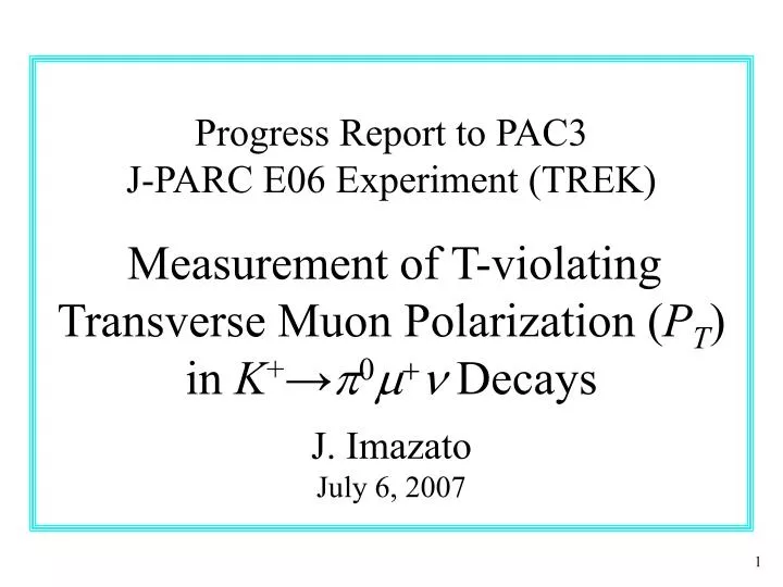
Progress Report to PAC3 J-PARC E06 Experiment (TREK) Measurement of T-violating Transverse Muon Polarization ( P T ) in K + → p 0 m + n Decays J. Imazato July 6, 2007. Problem assigned by PAC1.

E N D
Progress Report to PAC3J-PARC E06 Experiment (TREK)Measurement of T-violating Transverse Muon Polarization (PT) in K+→p0m+n DecaysJ. ImazatoJuly 6, 2007
Problem assigned by PAC1 The PAC would like the proponent to show that the improvement on the sensitivity and systematic uncertainty below 10-4 is attainable via detailed Monte Carlo studies, e.g. acceptance, B-field offset, detector misalignments and the new polarimeter.
Outline • Statistical sensitivity estimate • Systematic error estimate • Polarimeter misalignments • Other systematics • R&D for the detector upgrade • Collaboration/Cost/Funding/Beam • Summary
Transverse polarization in Km3 K+→p0m+ndecay • PT is T-odd and spurious effects from final state interaction are small.Non-zero PTis a signature of T violation. • Standard Model contribution to PT: PT(SM) < 10-7 • Spurious effects from final state interactions : PT(FSI) < 10-5 • There are theoretical models which allow sizeable PT • without conflicting with other experimental constraints.
PT measurement Use of upgraded E246 detector PT measured as the azimuthal asymmetry of the m+ decay e+ Ncw - Nccw Afwd(bwd) = ; AT = (Afwd - Abwd) / 2 Ncw - Nccw
Factors for statistical sensitivity _ • K+ beam intensity × Run time • K+ stopping efficiency (estop~0.30according to a MC ) • K+→p0m+n event rate with m+ in the polarimeter ❶ • E246 experience + MC calculation • m+→e+nn event rate with e+ detected, and polarization analyzing power : a = AT / PT❷ • MC calculation for the new active polarimeter In determining the sensitivity,❶and❷are separable. They are shown next step by step.
Positron asymmetry measurement • E246: • p0- forward (fwd) • and backward (bwd) • integral analysis • E06: • conservative estimate now by fwd/bwd • ambitious analysis including left/right • event-by-event analysis: future option
Optimume+measurement • PT = AT / a <cosqT> • a : analyzing power, • <cosqT> : attenuation factor • Figure of Merit (FoM) optimization by a MC simulation using a realistic m+ stopper condition FoM = AT√Ne+ • Eeth = 38 MeV • cosqeth = 0.34 • a = 0.38 (cf. 0.27 in E246)
Optimum p0 measurement • cosqT ≈ cosqp0 • up to finite m+ acceptance qm+ • cosqpth = 0.30 • <cosqp0> = 0.68 • PT = AT/ 0.258 • Optimization of qpth by FoM of • FoM = <cosqp0> √Npo
Km3 event rate and sensitivity • Standard event selection conditions as in E246 : • 65 < Mgg < 185 MeV/c2 • 3500 < M2TOF < 18,000 (MeV/c2)2 • pm+ <185 MeV/c • m+ incident into the polarimeter • qm+p0 < 160o • M2missing > -15,000 (MeV/c2)2 ⇒ Detector acceptanceW(Km3) = 1.14 ×10⁻² N(Km3) = N(K+)・estop・Br(Km3)・ W(Km3) = 3.3 × 10⁹ (total E06 good events) • MC calculation for 108 events and using PT =AT / 0.258 : dPT = 6.9 / √N(Km3) = 1.2 ×10⁻⁴
Summary of statistical sensitivity • dPT =1.2×10⁻⁴ for the fwd+bwd integral analysis compared with dPT = 1.8×10⁻⁴ given in the proposal . • Significant gain due to qe cut and realistic event selection (The effect of Ee+ threshold was partially included in the proposal.) • We will attack the event-by-event weighted analysis aiming for dPT = 1.0×10⁻⁴ (fwd+bwd) and dPT = 0.8×10⁻⁴ (including left+right).
Update of run time • K1.1-BR beam optics was changed due to B1 position 2005 design 2007 design • K+ beam intensity @ 9mA p on T1 is now 2.1×10⁶ /s • Necessary run time is now 1.4×10⁷ s. ( It was 1.0×10⁷ s in the proposal.) Acc = 6.0 msr %Dp/p Acc = 4.5 msr %Dp/p
E246 systematic errors Source of ErrorS12 fwd/bwddPTx 104e+ counter r-rotation x o 0.5e+ counter z-rotation x o 0.2e+ counter f-offset x o 2.8e+ counter r-offset o o <0.1e+ counter z-offset o o <0.1m+ counter f-offset x o <0.1MWPC f-offset (C4) x o 2.0CsI misalignment o o 1.6B offset (e) x o 3.0B rotation (dx) x o 0.4B rotation (dz) x x5.3K+ stopping distribution o o <3.0m+ multiple scattering x x7.1Decay plane rotation (qr) x o 1.2Decay plane rotation (qz) x x0.7Kp2 DIF background x o 0.6K+ DIF background o x < 1.9Analysis - - 3.8Total 11.4 • Cancellation by S12 and/or fwd/bwdalmost all systematics • except for : • m+ field alignment • m+ multiple scattering • decay plane shifts • due to • K+ stopping distribution • Detector inefficiency • distribution etc.
Suppression of systematic errors in E06 Old errors • m+ field alignment : dPT < 10-4 • PT analysis free from misalignment • m+ multiple scattering : dPT < 0 • no longer relevant with the active polarimeter • decay plane shifts : dPT < 10-4 • correction for PT only with statistical uncertainty • active polarimeter e+ analysis : dPT < 10-4 • Perfect fwd/bwd cancellation mechanism Newcomer • dPTsyst ~ 0.1 dPTsyst (E246) ~10-4
e+ asymmetrydue topolarimeter misalignment Rotation about Component r-axis z-axis Polarimeter erez Muon field drdz fwd - bwd : vanishes for er , ez , dr when t-integrated fwd - bwd : not vanishing for dz ! spurious AT ?
Misalignment analysis using Km3 Asymmetry analysis in terms of q0 : in plane spin angle from z-axis PT PT+dz PT+dr PT+dz+dr Asum(q0) Asub(q0) • Ddz ~ Ddr ~ 3×10⁻⁴ for misalignment determination • dPT < 1.2×10⁻⁴ for PT determination from Asub
Systematic error (1) associated withmisalignment analysis • Simulation calculation with: PT= 0 and dz = dr= 5o = 87 mr ==> dPT= (2±7)×10-4 for 108 events • Essentially statistical error of PT • No significant effect beyond the statistical error • In reality, dz ~ dr ~ 1 mr : • dPTsystshould be < 10-4 • PT can be deduced regardless of the existence of the polarimeter misalignments, er, ez, dr and dz. • But, how much is the systematic error induced in this misalignment analysis?
Systematic error (2) due to Kp2 BG Momentum resolutions Consistency MC simulation • Cancellation in gap integration • ==> averaging to < 1/10 (<0.02%) • p0 - fwd/bwd cancellation ==> suppression to < 1/10 (<0.002%) dPT < 10-4 • Dangerous p+ -> m+n background with a PT component • Substantial reduction due to the addition of the C0 chamber
Systematic error (3) associated with decay plane rotation correction • Two rotation angles of qz and qr • Relation: dPT ~ 0.5 <q>due to PN and PL admixture • <qr> isfwd/bwd cancelling, but <qz> isnot fwd/bwd cancelling. • PTwill be corrected for <qz> and <qr> qz distribution in E246 <qz>= -0.004±0.12 mr • Statistical error of the correction • d<qz> = s(qz) /√Ntotal • dPT (<qz>) ≪dPTstat ~ 10-4 dPT (<qz>) ≪ 10-4 dPT (<qr>) ~dPTstat&fwd/bwd ≪ 10-4 -1 0 +1 0
Systematic errors (4) associated with positron analysis • Systematics in the chamber measurement is left-right canceling : • cell inefficiency • plate non-uniform thickness • etc. • further cancellation by fwd-bwd up to small Dr = rfwd - rbwd • symmetrization of r with bias • rfwd(r,y,z) = rbwd(r,y,z) • PTfwd = PT + dPT’ • PTbwd = -PT+ dPT” No problem • Cancellation power will be calculated using data. m+ stopping distribution in the stopper Dr = rfwd - rbwd was a few % in E246 dPTshould be < 10-4
Stopper mSR study (Canada, Japan) • Muon spin behavior was studied for candidate stopper materials Typical TF precession pattern • TRIUMF surface muon beam with full polarization • E1120 experiment to study mSR in Al and Mg alloys • Transverse field (TF) and longitudinal field (LF) relaxation rates were measured with a 0.03 T field. • Several candidate stopper materials were confirmed. Al alloys: A5052, A6063, Mg alloys: AZ31, ZK60, Z6, AM60, AZ91
CsI(Tl) readout (INR) • First application of APD readout to a large CsI(Tl) calorimeter Cosmic ray test Energy Timing st =3ns • Very good timing characteristics were confirmed
Fiber target (INR, KEK) • Target cross section • Light yield test of the fiber Pulse height spectrum Pulse shape • 2.5x2.5 mm x 20 cm fiber • Tapered coupling to MPPC • Yield of ~ 20 p.e. for 90Sr 20 cm + clear fiber + MPPC • MPPC radiation hardness test at RCNP • Increasing leakage current with dose • Design of shielding
C0 and C1 GEM chambers (MIT) • Three chambers were beam-tested • at FNAL by MIT GEM Lab. H- and V-amplitude correlation Middle residual • Stable operation • Resolution of • Dx = 90 mm • Rate capability • Readout electronics Amplitude vertical Amplitude horizontal Residualx(mm)
Muon field magnet (KEK) TOSCA 3D calculation
Collaboration • International cooperation in detector construction • Canada Univ. of Saskatchewan, Univ. of British Columbia, TRIUMF, Univ. of Montreal • U.S.A. MIT, Iowa State Univ., Univ. of South Carolina • Japan KEK, Osaka Univ., Tohoku Univ., Kyoto Univ., NDA - New participation - • Russia INR (group with E246 experience)Altogether • Vietnam Nat. Sci. Univ. in HCMC 35 people • Strong support from : (1) TRIUMF detector shop, and • (2) MIT GEM Lab.
Beamline preparation K1.1 • K1.1BR uses the upstream part of K1.1. • No budget is allocated for K1.1 in the • J-PARC budget, although it is one of the • planned secondary lines in Phase 1. • We would like to go ahead with the BR • (700-800 MYen), with a possible Canadian • contribution to the 0.8 GeV leg. • Once full beam operation has started at T1, it will become very difficult to install the frond end of the channel • (B1, Q1, Q2, B2). Timely installation • of K1.1/K1.1BR is absolutely necessary. K1.1-BR T1
Cost estimate and funding policy • Updated cost estimate : • Detector upgrade etc. 279,710 kYen • Transfer of the SC spectrrometer 182,000 kYen • K1.1BR branch construction 50,000 kYen (These are not very different from the estimates in the proposal.) • Policy for funding :
Time schedule • Totally dependent on the K1.1-BR beamline installation and funding of the experiment. • In the proposal we presented: 20091) Spectrometer setup 2) Field mapping 3) Detector setup 4) Beam tuning 2010-11 5) Engineering run, and 6) Data taking • We would like to pursue the earliest possible schedule aiming to provide the first particle physics output from the hadron hall.
Theory impact • A clean search for CP violation via Higgs dynamics. • Direct CP violation presumably unsuppressed by DI=1/2 rule PT ~ [e’/e effect]× 20 = 5 x 10-6× 20 ~ 10-4 -- unless enhanced couplings to leptons! (I. Bigi, CERN Flavor WS, 2007 )
Summary • We have shown with MC studies that E06 can reach at least the statistical sensitivity of dPT =1.2×10⁻⁴ in the safe fwd+bwd integral analysis. • We have established a PT extraction method in the presence of any polarimeter misalignments. • We have shown that other systematics should be controllable to the level < 10-4. • We have demonstrated the validity of the proposed upgraded detector elements with necessary test experiments.
Our request to PAC • The Canadian and American groups are starting budget requests in their countries. The status of stage-2 approval is very necessary for a successful application. The PAC is requested to consider E06 for the stage-2 approval although there are no funds yet in place. • An endorsement of the K1.1BR beamline installation for E06 is desirable. The PAC is also asked to make a strong recommendation to the IPNS/J-PARC management to provide a plan for the K1.1BR construction so that the Canadian group will be able to request money for a contribution to this stopped K+ beamline. PAC3
K+Stopping efficiency GEANT3 calculation • Optimum degrader thickness • Target diameter of • d=8cm • d=6cm • d=4cm • FOM is maximum at 800 MeV/c • estop=0.25~0.30
Stopped beam method • Double ratio experiment • AT = (Afwd - Abwd) / 2 • Ncw - Nccw • Afwd(bwd) = • Ncw - Nccw • PT = AT / {a <cosqT>} • a : analyzing power • <cosqT> : attenuation factor • Imx = PT / KF • KF :kinematic factor PT = - 0.0017 ± 0.0023(stat) ± 0.0011(syst) ( |PT | < 0.0050 : 90% C.L. ) Imx = - 0.0053 ± 0.0071(stat) ± 0.0036(syst) ( |Imx | <0.016 : 90% C.L. ) bwd -p0 (g ) fwd -p0 (g ) Statistical error dominant
Target of E06 • E246 detector is upgraded for E06
Sensitivity improvement in E06 • We aim at a sensitivity of dPT ~10-4 • dPTstat ~0.05 dPTstat (E246) ~10-4 with 1) ×30 beam intensity, 2) ×10 detector acceptance, and • Higher analyzing power dPTsyst ~ 0.1 dPTsyst (E246) ~10-4by 1) Precise calibration of misalignments using data 2) Correction of systematic effects • Precise fwd-bwd cancellation of systematics by data symmetrization (Estimate of cancellation power using data) • Most crucial systematics are misalignment of : Muon polarimeter and muon field distribution
E246 muon polarimeter One-sector view Cross section B y(cm) _ m+ →e+ne nm W(e+) ∝ 1 + A cos q • Passive polarimeter with • Al muon stopper • Left/Right positron counters • simple analysis and systematics
Active muon stopoper • Identification of muon stopping point/ decay vertex • Measurement of positron energy Ee+ and angle qe+ • Large positron acceptance of nearly 4p • Larger analyzing power • Higher sensitivity • Lower BG in positron spectra • Parallel plate stopper with • Gap wire chambers Number of plates 31 Plate material Al, Mg or alloy Plate thickness ~ 2 mm Plate gap ~ 8 mm Ave. density 0.24 rAl m+ stop efficiency ~ 85% • Small systematics for L/Re+ asymmetry measurement • Fit for p0fwd/bwd measurement • Simple structure
Tracking system • E246 J-PARC E06 • C0 (cylindrical) and C1(planer) are GEM chambers
Rad.hardness test of MPPC • MPPC 400 pixel type • Irradiation of up to 36 Gy • Increase of leakage current proportional to dose
Beam halo simulation • GEANT4 simulation • 10 cm-f BeO degrader + 6 cm-fTarget K+ flux distribution p+ m+ e+ n
CsI(Tl) readout • CsI(Tl) + APD+ Amplifier + FADC • Electrons after APD : ~ 2 ×10⁷ @ 100 MeV • Max count rate / module : ~ 100 kHz • Max K+ decay rate : ~ 20 MHz - enough for the beam intensity in Phase 1 • Noise level : to be tested • Module energy resolution : to be tested • Energy resolution is determined by lateral shower • leakage