Download
1 / 26
260 likes | 391 Views
Advanced divertor configurations with large flux expansion. V. A. Soukhanovskii Lawrence Livermore National Laboratory, Livermore, California, USA H. Reimerdes

E N D
Advanced divertor configurations with large flux expansion V. A. Soukhanovskii Lawrence Livermore National Laboratory, Livermore, California, USA H. Reimerdes EcolePolytechniqueFédérale de Lausanne, Centre de Recherches en Physique des Plasmas, Association EuratomConfédération Suisse, Lausanne, Switzerland NSTX-U and TCV Research Teams
Acknowledgements D. D. Ryutov, A. McLean, E. Meier, T. D. Rognlien, M. V. Umansky(LLNL), D. Battaglia, R. E. Bell, A. Diallo, S. P. Gerhardt, R. Kaita, S. M. Kaye, E. Kolemen, B. P. LeBlanc, J. E. Menard, D. Mueller, S. F. Paul, M. Podesta, A. L. Roquemore, F. Scotti (PPPL), R. Maingi(ORNL), R. Raman (U Washington) G.P. Canal, B. Labit, W. Vijvers, S. Coda, B.P. Duval (CRPP) T. Morgan, J. Zielinski, G. De Temmerman (DIFFER) B. Tal (WIGNER)
Outline: Experimental studies of snowflake divertor configuration in NSTX and TCV • Tokamak divertor challenge • Snowflake divertor configuration • Snowflake divertor in NSTX and TCV • Magnetic properties and control • H-mode confinement and pedestal • Divertor heat flux mitigation and partitioning • Modeling • Conclusions and outlook
Various techniques developed for reduction of heat fluxes q|| (divertor SOL) and qpeak (divertor target) • Recent ideas to improve standard divertor geometry • Snowflake divertor (D. D. Ryutov, PoP 14, 064502 2007) • X-divertor (M. Kotschenreutheret. al, IC/P6-43, IAEA FEC 2004) • Local (strike point) flux expansion • Super-X divertor (M. Kotschenreutheret. al, IC/P4-7, IAEA FEC 2008) • Local (strike point) flux expansion at large R (major radius) • Being implemented in MAST Upgrade • See T. Petrie et al., Talk O36 on Friday, 25 May 2012
Snowflake divertor geometry is “advanced” w.r.t. standard X-point divertor Exact snowflake divertor * + + + + snowflake-minus snowflake-plus D. D. Ryutov, PoP 14, 064502 2007 • Snowflake divertor • Second-order null • Bp ~ 0 and grad Bp ~ 0 (Cf. first-order null: Bp ~ 0) • Obtained with existing divertor coils (min. 2) • Exact snowflake topologically unstable • Deviation from ideal snowflake: s = d / a • d – distance between nulls, a – plasma minor radius • Predicted geometry properties (cf. standard divertor) • Increased edge shear: ped. stability • Add’l null: H-mode power threshold, ion loss • Larger plasma wetted-area Awet : reduce qdiv • Four strike points : share qII • Larger X-point connection length Lx : reduce qII • Larger effective divertor volume Vdiv : incr. Prad, PCX • Experiments: TCV and NSTX
Outline: Experimental studies of snowflake divertor configuration in NSTX and TCV • Tokamak divertor challenge • Snowflake divertor configuration • Snowflake divertor in NSTX and TCV • Magnetic properties and control • H-mode confinement and pedestal • Divertor heat flux mitigation and partitioning • Modeling • Conclusions and outlook
NSTX and TCV: Snowflake divertor configurations obtained with existing divertor coils TCV • Conventional aspect ratio A=3.5-3.7 • Ip≤ 1.0 MA, BT ≤ 1.5 T • Pin ≤ 4.5 MW (ECH) • Graphite PFCs • Open divertor (not optimized) • Create magnetic configuration (SF, SF+, SF-) with shaping coils
TCV: Investigate the characteristics of the entire range of snowflake configurations [F. Piras, et al., Plasma Phys. Control. Fusion. 51 (2009) 055009] • Evaluate fexp and CL at location of max. fexp • Variable configuration: vary location of X-points over a wide range • All configurations are obtained under feed-forward control • Experiments have so far focused on SF+ • Investigate possibility to distribute exhaust power on more than the two strike points
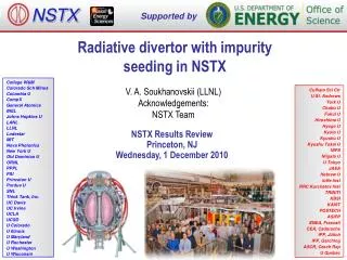
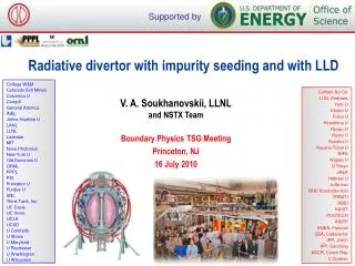
NSTX and TCV: Snowflake divertor configurations obtained with existing divertor coils • Aspect ratio A=1.4-1.5 • Ip ≤ 1.4 MA, BT= 0.45 T • Pin ≤ 7.4 MW (NBI) • lq = 5-10 mm • High divertor heat flux • qpeak ≤ 15 MW/m2 • q||≤ 200 MW/m2 • Open divertor • Graphite PFCs with lithium coatings • Asymmetric snowflake-minus s = 0.4-0.5
NSTX: Plasma-wetted area and connection length are increased by 50-90 % in snowflake divertor • These properties observed in first 30-50 % of SOL width (lq~6 mm) • Btot angles in the strike point region: 1-2o, sometimes < 1o • Concern for hot-spot formation and sputtering from divertor tile edges • Can be alleviated by q|| reduction due to radiative detachment and power partitioning between strike points
Close-loop feedback control of divertor coil currents is desirable for steady-state snowflake M.A. Makowski & D. Ryutov, “X-Point Tracking Algorithm for the Snowflake Divertor” • All configurations are obtained reproducibly under feed-forward control in TCV and NSTX • In NSTX • Developed X-point tracking algorithm that locates nulls and centroid • Algorithm tested on NSTX snowflakes successfully • Implementing snowflake control in digital plasma control system • Collaboration between NSTX-U and DIII-D
Outline: Experimental studies of snowflake divertor configuration in NSTX and TCV • Tokamak divertor challenge • Snowflake divertor configuration • Snowflake divertor in NSTX and TCV • Magnetic properties and control • H-mode confinement and pedestal • Divertor heat flux mitigation and partitioning • Modeling • Conclusions and outlook
NSTX: good H-mode confinement properties and core impurity reduction obtained with snowflake divertor • 0.8 MA, 4 MW H-mode • k=2.1, d=0.8 • Core Te ~ 0.8-1 keV, Ti ~ 1 keV • bN~ 4-5 • Plasma stored energy~ 250 kJ • H98(y,2) ~ 1 (from TRANSP) • ELMs • Suppressed in standard divertor H-mode via lithium conditioning • Re-appeared in snowflake H-mode • Core carbon reduction due to • Type I ELMs • Edge source reduction • Divertor sputtering rates reduced due to partial detachment
TCV: Snowflake configuration leads to an improved kink-ballooning stability [F. Piras, et al., Phys. Rev. Lett. 105 (2010) 155003] • H-mode threshold unchanged (power and density dependence) • Modest confinement improvement (may be due to increased core shaping) • Frequency of type-I ELMs decreases • Experiment consistent with improved kink-ballooning stability • Even though energy loss per ELM increase, the average energy lost through ELMs decreases significantly
Outline: Experimental studies of snowflake divertor configuration in NSTX and TCV • Tokamak divertor challenge • Snowflake divertor configuration • Snowflake divertor in NSTX and TCV • Magnetic properties and control • H-mode confinement and pedestal • Divertor heat flux mitigation and partitioning • Modeling • Conclusions and outlook
NSTX: Access to radiative detachment with intrinsic carbon in snowflake divertor facilitated • Snowflake divertor (*): PSOL~3-4 MW, fexp~40-60, qpeak~0.5-1.5 MW/m2 • Low detachment threshold • Detachment characteristics comparable to PDD with D2 or CD4 puffing
NSTX: Significant reduction of divertor heat flux observed between ELMs in snowflake divertor • Divertor C III and C IV brightness profiles broaden • Attached standard divertor -> snowflaketransition-> snowflake + detachment • PSOL ~ 3 MW (PNBI = 4 MW) • Qdiv~ 2 MW -> Qdiv ~ 1.2 MW -> Qdiv ~ 0.5-0.7 MW
NSTX: Impulsive heat loads due to Type I ELMs are mitigated in snowflake divertor • H-mode discharge, WMHD ~ 220-250 kJ • Type I ELM (DW/W ~ 5-8 %) re-appeared • ELM peak heat flux decreased • Theory and modeling highlight (T. D. Rognlien et al., P1-031) • Reduced surface heating due to increased ELM energy deposition time • Convective mixing of ELM heat flux in null-point region -> heat flux partitioning between separatrix branches
TCV: In L-mode s has to be small to activate a secondary strike point • Heat flux estimate from Langmuir probes (LP) • SF+ configuration: secondary strike points are in the private flux region of the primary separatrix • Sigma scan in Ohmic L-mode shows activation of the secondary strike points (PSP3/PSP1~10%) only for small values of sigma (s<0.2)
TCV: ELMs activate secondary strike points at larger values of s • Measure transient heat fluxes during ELMs in ECH H-modes with fast infra-red (IR) cameras • Sampling time ≥ 40ms • Secondary strike point (SP3) receives significant power at relatively large values of sigma • Power redistribution during ELMs consistent with poloidal beta-driven convection around the null-point [D.D. Ryutov, et al., APS DPP 2011]
Outline: Experimental studies of snowflake divertor configuration in NSTX and TCV • Tokamak divertor challenge • Snowflake divertor configuration • Snowflake divertor in NSTX and TCV • Magnetic properties and control • H-mode confinement and pedestal • Divertor heat flux mitigation and partitioning • Modeling • Conclusions and outlook
UEDGE modeling shows a trend toward reduced temperatures, heat and particle fluxes in snowflake divertor • 2D multi-fluid code UEDGE • Fluid (Braginskii) model for ions and electrons • Fluid for neutrals • Classical parallel transport, anomalous radial transport • D = 0.25 m2/s • ce,i = 0.5 m2/s Core interface: • Te,i = 120 eV • ne = 4.5 x 10¹⁹ Rrecy = 0.95 Carbon 3 %
Snowflake geometry is a leading heat flux mitigation candidate for NSTX-U NSTX-U snowflake simulation • Challenge for NSTX-U divertor • 2-3 X higher input power (PNBI< 12 MW, Ip < 2 MA • 30-50 % reduction in n/nG • 3-5 X longer pulse duration • Projected NSTX-U peak divertor heat fluxes up to 25-40 MW/m2 • Snowflake divertor projections to NSTX-U optimistic • UEDGE modeling shows radiative detachment of all snowflake cases with 3% carbon and up to PSOL~11 MW • qpeak reduced from ~15 MW/m2 (standard) to 0.5-3 MW/m2 (snowflake)
TCV and NSTX studies suggest the snowflake divertor configuration may be a viable divertor solution for present and future tokamaks • NSTX • Core H-mode confinement unaffected, core carbon reduced • Pedestal stability modified: Type I ELMs re-appeared • Divertor heat flux significantly reduced • Steady-state reduction due to geometry and radiative detachment • ELM heat flux reduction due to power sharing, radiation and geometry • Proposing experiments and control development at DIII-D, planning snowflake divertor for NSTX-U • TCV • Can create a wide range of snowflake configurations • Heat flux at a secondary strike point increases with decreasing s • ELMs activate secondary strike point at larger values of s • Improved edge stability leading to less frequent TypeI ELMs • Current upgrades will improve heat flux measurements at the target • Additional Langmuir probe array will also cover LFS strike point • Improved IR system will allow ELM resolved measurements
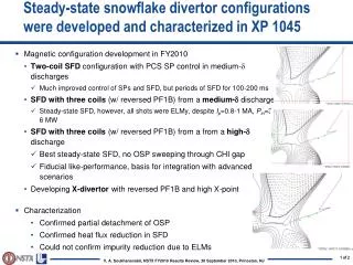
Impulsive heat loads due to Type I ELMs are mitigated in snowflake divertor Steady-state At ELM peak • H-mode discharge, WMHD ~ 220-250 kJ • Type I ELM (W/DW ~ 5-8 %)