Download
1 / 45
450 likes | 588 Views
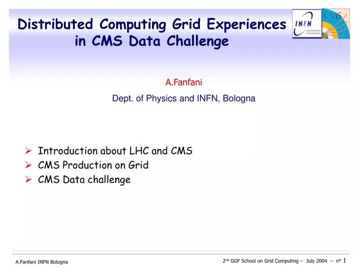
Distributed Computing Grid Experiences in CMS Data Challenge. Introduction about LHC and CMS CMS Production on Grid CMS Data challenge. A.Fanfani Dept. of Physics and INFN, Bologna. Introduction. Large Hadron Collider CMS (Compact Muon Solenoid) Detector CMS Data Acquisition

E N D
Distributed Computing Grid Experiences in CMS Data Challenge • Introduction about LHC and CMS • CMS Production on Grid • CMS Data challenge A.Fanfani Dept. of Physics and INFN, Bologna
Introduction Large Hadron Collider CMS (Compact Muon Solenoid) Detector CMS Data Acquisition CMS Computing Activities
Proton- Proton Collision Beam energy : 7 TeV Luminosity : 1034 cm-2 s-1 Data taking : > 2007 Large Hadron Collider LHC bunch-crossing rate: 40 MHz 20 p-p collisions for each bunch-crossing p-p collisions 109 evt/s ( Hz )
p p CMS detector
High Level Trigger – PCs data CMS Data Acquisition 1event is 1MB in size Bunch crossing 40 MHz GHz ( PB/sec) Online system Level 1 Trigger - special hardware • multi-level trigger to: • filter out not interesting events • reduce data volume 75 KHz (75 GB/sec) 100 Hz (100 MB/sec) data recording Offline analysis
CMS Computing • Large amounts of events will be available when the detector will start collecting data • Large scale distributed Computing and Data Access • Must handle PetaBytes per year • Tens of thousands of CPUs • Tens of thousands of jobs • heterogeneity of resources : hardware, software, architecture and Personnel • Physical distribution of the CMS Collaboration
CMS Computing Hierarchy 1PC* PIII 1GHz PB/sec 100MB/sec Offline farm recorded data Online system • Filterraw data • Data Reconstruction • Data Recordin • Distribution to Tier-1 CERN Computer center Tier 0 10K PCs* . . • Permamnet data storage and management • Data-heavy analysis • re-processing • Simulation • ,Regional support Italy Regional Center Fermilab Regional Center France Regional Center Tier 1 2K PCs 2.4 Gbits/sec . . . Tier 2 • Well-managed disk storage • Simulation • End-user analysis Tier2 Center Tier2 Center Tier2 Center 500 PCs 0.6 – 2. Gbits/sec workstation Tier 3 InstituteA InstituteB 100-1000 Mbits/sec
CMS Production and Analysis • The maincomputing activity of CMS is currently related to the simulation, with Monte Carlo based programs, of how the experimental apparatus will behave once it is operational • Long term need of large-scale simulation efforts to : • optimise the detectors and investigate any possible modifications required to the data acquisition and processing • better understand the physics discovery potential • perform large scale test of the computing and analysis models • The preparation and building of the Computing System able to treat the data being collected pass through sequentially planned steps of increasing complexities (Data Challenges)
Ntuple files (Hbook zebra) zebra files POOL files m+ m- Z p p H Z e+ e- POOL files CMS MonteCarlo production chain Generation CMKIN:MonteCarlo Generation of the proton-proton interaction, based on PYTHIA CPU time depends strongly on the physical process • CMSIM/OSCAR:Simulation of tracking in the CMS detector, based on GEANT3/GEANT4(=toolkit for the simulation of the passage of particles through matter) • very CPU intensive, non-negligible I/O requirement Simulation • ORCA: • reproduction of detector signals (Digis) • simulation of trigger response • reconstruction of physical information for final analysis • POOL (Pool Of persistent Object for LHC) • used as persistency layer Digitization Reconstruction Analysis
Generation Simulation 25Hz Reconstruction Reco Data Tier-1 Tier-1 Reco Data Reco Data Analysis Analysis Tier-2 Tier-2 Tier-2 Analysis CMS Data Challenge 2004 Planned to reach a complexity scale equal to about 25% of that foreseen for LHC initial running • Pre-Challenge Production in 2003/04 • Simulation and digitization of70 Million events needed as input for the Data Challenge • Digitization is still running • 750K jobs, 3500 KSI2000 months, 700 Kfiles,80 TB of data • Classic and Grid (CMS/LCG-0, LCG-1, Grid3) productions • Data Challenge (DC04) • Reconstruction of data for sustained period at 25Hz • Data distribution to Tier-1,Tier-2 sites • Data analysis at remote sites • Demonstrate the feasibility of the full chain PCP Digitization DC04 Tier-0
CMS Production Prototypes of CMS distributed production based on grid middleware used within the official CMS production system: Experience on LCG Experience on Grid3
CMS ‘permanent’ production Pre DC04 start DC04 start # Datasets/month … ‘Spring02 prod’ ‘Summer02 prod’ CMKIN CMSIM + OSCAR Digitisation 2002 2003 2004 The system is evolving into a permanentproduction effort…
CMS Production tools • CMS production tools (OCTOPUS) • RefDB • Central SQL DB at CERN. Contains production requests with all needed parameters to produce the dataset and the details about the production process • MCRunJob (or CMSProd) • Tool/framework for job preparation and job submission. Modular (plug-in approach) to allow running both in a local or in a distributed environment (hybrid model) • BOSS • Real-time job-dependent parameter tracking. The running job standard output/error are intercepted and filtered information are stored in BOSS database. • Interface the CMS Production Tools to the Grid using the implementations of many projects: • LHC Computing Grid (LCG), based on EU middleware • Grid3, Grid infrastructure in the US
Dataset metadata RLS Computer farm JDL Grid (LCG) Scheduler LCG-0/1 DAG Grid3 DAGMan (MOP) Job metadata job Push data or info Chimera VDL Virtual Data Catalogue job job Planner Pull info job Pre-Challenge Production setup Phys.Group asks for a new dataset RefDB shell scripts Data-level query Local Batch Manager BOSS DB Job level query McRunjob + plug-in CMSProd Site Manager starts an assignment
CMS/LCG Middleware and Software • Use as much as possible the High-level Grid functionalities provided by LCG • LCG Middleware • Resource Broker (RB) • Replica Manager and Replica Location Service (RLS) • GLUE Information scheme and Information Index • Computing Elements (CEs) and Storage Elements (SEs) • User Interfaces (UIs) • Virtual Organization Management Servers (VO) and Clients • GridICE Monitoring • Virtual Data Toolkit (VDT) • Etc. • CMSsoftware distributed as rpms and installed on the CE • CMSProduction tools installed on UserInterface
Dataset metadata CE CMS sw JDL SE CE CE CMS sw WN X read/write Job metadata Push data or info Pull info CMS production components interfaced to LCG middleware • Production is managed from theUser Interface with McRunjob/BOSS CMS LCG RefDB RLS SE UI RB McRunjob SE bdII BOSS CE SE • Computing resources are matched by the Resource Broker to the job requirements (installed CMS software, MaxCPUTime, etc) • Output data stored into SE and registered in RLS
distribution of jobs: executing CEs Nb of jobs Executing Computing Element 1 month activity Nb of jobs in the system
Resources: About 170 CPU’s and 4TB CMS/LCG-0 Sites: Bari,Bologna, CNAF, EcolePolytecnique, Imperial College, Islamabad,Legnaro, Taiwan, Padova,Iowa LCG-1 sites of “south testbed” (Italy-Spain)/Gridit Production on grid: CMS-LCG Nb of events Gen+Sim on LCG Assigned —— Produced —— CMS-LCGRegional Center Statistics - 0.5 Mevts “heavy” CMKIN: ~2000 jobs ~8 hours each - 2.1 Mevts CMSIM+OSCAR: ~8500 jobs ~10hours each ~2 TB data CMS/LCG-0 LCG-1 Date Aug03 Dec 03 Feb 03
LCG: results and observations • CMS Official Production on early deployed LCG implementations • 2.6 Milions of events ( 10K long jobs), 2TB data • Overall Job Efficiency ranging from 70% to 90% • The failure rate varied depending on the incidence of some problems: • RLS unavailability few times, in those periods the job failure rates could increase up to 25-30% single point of failure • Instability due to site mis-configuration, network problems, local scheduler problem, hardware failure with overall inefficiency about 5-10% • Few % due to service failures • Success Rate on LCG-1 was lower wrt CMS/LCG-0 (efficiency 60%) • less control on sites, less support for services and sites (also due to Christmas) • Major difficulties identified in the distributed sites consistent configuration • Good efficiencies and stable conditions of the systemin comparison with what obtained in previous challenges • showing the maturity of the middleware and of the services, provided that a continuous and rapid maintenance is guaranteed by the middleware providers and by the involved site administrators
USCMS/Grid3 Middleware& Software • Use as much a possible the low-level Grid functionalities provided by basic components • A Pacman package encoded the basic VDT-based middleware installation, providing services from: • Globus (GSI, GRAM, GridGFTP) • Condor (Condor-G, DAGMan,…) • Information service based on MDS • Monitoring based on MonaLisa + Ganglia • VOMS from EDG project • Etc. • Additional services can be provided by the experiment, i.g. • Storage Resource Manager (SRM), dCache for storing data • CMSProduction tools on MOP master
Globus DAGMan Condor-G mop_submitter Globus Globus Globus CMS/Grid3 MOP Tool • Mop_submitter wraps McRunjob jobs in DAG format at the “MOP master” site • DAGMan runs DAG jobs through remote sites’ Globus JobManagers through Condor-G • Condor-based match-making process selects resources • Results are returned using GridFTP to dCache at FNAL • Job created/submitted from MOP Master Remote Site 1 Batch Queue MOP (MOnteCarlo distributed Production) is a system for packaging production processing jobs into DAGMan format Master Site computer nodes GridFTP McRunjob GridFTP Remote Site N FNAL Batch Queue computer nodes GridFTP
150 days period from Nov-03 Production on Grid: Grid3 Number of events per day Distribution of usage (in CPU-days) by site in Grid2003
USMOP Regional Center Statistics - 3 Mevts CMKIN: ~3000 jobs ~ 2.5min each - 17 Mevts CMSIM+OSCAR: ~17000 jobs ~ few days each (20-50h), ~12 TB data Resources: US CMS Canonical resources (Caltech,UCSD,Florida,FNAL ) 500-600 CPUs Grid3 shared resources (17 sites) over 2000 CPUs (shared) realistic usage (few hundred to 1000) Production on Grid: Grid3 Nb of events Simulation on Grid3 Assigned —— Produced —— Date Aug 03 Jul 04 Nov 03
Grid3: results and observations • Massive CMS Official Production on Grid3 • 17Milions of events (17K very long jobs), 12TB data • Overall Job Efficiency 70% • Reasons of job failures • CMS application bugs ~ few % • No significant failure rate from Grid middleware per se • can generate high loads • infrastructure relies on shared filesystem • Most failures due to “normal” system issues • hardware failure • NIS, NFS problems • disks fill up • Reboots • Service level monitoring need to be improved • a service failure may cause all the jobs submitted to a site to fail
CMS Data Challenge CMS Data Challenge overview LCG-2 components involved
Definition of CMS Data Challenge 2004 • Aim of DC04 (march-april): • reach a sustained 25Hz reconstruction rate in the Tier-0 farm (25% of the target conditions for LHC startup) • register data and metadata to a catalogue • transfer the reconstructed data to all Tier-1 centers • analyze the reconstructed data at the Tier-1’s as they arrive • publicize to the community the data produced at Tier-1’s • monitor and archive of performance criteria of the ensemble of activities for debugging and post-mortem analysis • Not a CPU challenge, but a full chain demonstration!
Tier-0 data distribution agents Tier-1 Export Buffer Tier-2 Tier-2 Tier-2 Tier-1 agent Physicist Physicist Physicist MSS T1 storage T2 storage T2 storage T2 storage ORCA Analysis Job Tier-1 ORCA Local Job ORCA Local Job ORCA Local Job Tier-1 agent MSS T1 storage ORCA Analysis Job DC04 layout Tier-0 General DistributIon Buffer LCG-2 Services ORCA RECO Job RefDB IB TMDB Transfer Management 25Hz fake on-line process POOL RLS catalogue Castor
Main Aspects • Reconstruction at Tier-0 at 25Hz • Data Distribution • an ad-hoc developed Transfer Management DataBase (TMDB) has been used • a set of transfer agents communicating through the TMDB • The agent system was created to fill the gap in EDG/LCG middleware for mechanism for large-scale(bulk) scheduling of transfers • Support a (reasonable) variety of data transfer tools • SRB Storage Resource Broker • LCG Replica Manager • SRM Storage Resource Manager • Each with an agent at Tier-0 copying data to the appropriate Export Buffer (EB) • Use a single file catalogue (accessible from Tier-1’s) • RLS used for data and metadata by all transfer tools • Monitor and archive resource and process information • MonaLisa used on almost all resources • GridICE used on all LCG resources (including WN’s) • LEMON on all IT resources • Ad-hoc monitoring of TMDB information • Job submission at Regional Centers to perform analysis FNAL T1 SRM Export Buffer dCache/Enstore MSS General Buffer CNAF T1 LCG SE Export Buffer PIC T1 CASTOR MSS SRB Export Buffer Lyon T1 RAL T1 GridKA T1 CERN Tier-0 CASTOR, HPSS, Tivoli MSS
Processing Rate at Tier-0 • Reconstruction jobs at Tier-0: produce data and register them into RLS Tier-0 Events • Processed about 30M events • Generally kept up at T1’s in CNAF, FNAL, PIC Event Processing Rate • Got above 25Hz on many short occasions • But only one full day above 25Hz with full system
LCG-2 in DC04 Aspects of DC04 involving LCG-2 components • register all data and metadata to a world-readable catalogue • RLS • transfer the reconstructed data from Tier-0 to Tier-1 centers • Data transfer between LCG-2 Storage Elements • analyze the reconstructed data at the Tier-1’s as data arrive • Real-Time Analysis with ResourceBroker on LCG-2 sites • publicize to the community the data produced at Tier-1’s • straightforward using the usual Replica Manager tools • end-user analysis at the Tier-2’s (not really a DC04 milestone) • first attempts • monitor and archive resource and process information • GridICE • Full chain (but the Tier-0 reconstruction) done in LCG-2
Description of CMS/LCG-2 system • RLS at CERN with Oracle backend • Dedicated information index (bdII) at CERN (by LCG) • CMS adds its own resources and removes problematic sites • Dedicated Resource Broker at CERN (by LCG) • Other RB’s available at CNAF and PIC, in future use them in cascade • Official LCG-2 Virtual Organization tools and services • Dedicated GridICE monitoring server at CNAF • Storage Elements • Castor SE at CNAF and PIC • Classic disk SE at CERN (Export Buffer), CNAF, PIC, Legnaro, Taiwan • Computing Elements at CNAF, PIC, Legnaro, Ciemat, Taiwan • User Interfaces at CNAF, PIC, LNL
RLS usage • CMS framework uses POOL catalogues with file information by GUID • LFN • PFNs for every replica • Meta data attributes • RLS used as a global POOL catalogue, with full file meta data • Global file catalogue(LRC component of RLS: GUID PFNs) • Registration of fileslocation by reconstruction jobs and by all transfer tools • Query by the Resource Broker to submit analysis jobs close to the data • Global metadata catalogue (RMC component of RLS: GUID metadata) • Meta data schema handled and pushed into RLS catalogue by POOL • Some attributes are highly CMS-specific • Query (by users or agents) to find logical collection of files • CMS does not use a separate file catalogue for meta data • Total Number of files registered in the RLS during DC04: • 570K LFNs each with 5-10 PFN’s • 9 metadata attributes per file (up to ~1 KB metadata per file)
Time to register the output of a Tier-0 job (16 files) 2sec/file RLS issues • Inserting information into RLS: • insert PFN (file catalogue) was fast enough if using the appropriate tools, produced in-course • LRC C++ API programs (0.1-0.2sec/file), POOL CLI with GUID (secs/file) • insert files with their attributes (file and metadata catalogue) was slow • We more or less survived, higher data rates would be troublesome • Querying information from RLS • Looking up file information by GUID seems sufficiently fast • Bulk queries by GUID take a long time (seconds per file) • Queries on metadata are too slow (hours for a dataset collection) Sometimes the load on RLS increasesand requires intervention on the server (i.g. log partition full,switch of server node, un-optimized queries) able to keep up in optimal condition, so and so otherwise 2 Apr 18:00 5 Apr 10:00
RLS current status • Important performance issues found • Several workarounds or solutions were provided to speed up the access to RLS during DC04 • Replace (java) replica manager CLI with C++ API programs • POOL improvements and workarounds • Index some meta data attributes in RLS (ORACLE indices) • Requirements not supported during DC04 • Transactions • Small overhead compared to direct RDBMS catalogues • Direct access to the RLS Oracle backend was much faster (2min to suck the entire catalogue wrt several hours) • Dump from a POOL MySQL catalogue is minimum factor 10 faster than dump from POOL RLS • Fast queries • Some are being addressed • Bulk functionalities are now available in RLS with promising reports • Transactions still not supported • Tests of RLS Replication currently carried out • ORACLE streams-based replication mechanism
Tier-2 Data management Tier-0 Transfer Management DB RLS • Data transfer between LCG-2 Storage Elements using the Replica Manager based agents • Data uploaded at Tier-0 in an Export Buffer being a disk based SE and registered in RLS • Data transfer from Tier-0 to CASTOR SEs at Tier-1 (CNAF and PIC) • Data replication from Tier-1 to Tier-2 disk SEs • Comments • No SRM based SE used since compliant RM was not available • Replica manager command line (java startup) can introduce a not negligible overhead • Replica manager behavior under error condition needs improvement (a clean “rollback” is not always granted and this requires ad-hoc checking/fixing) CERN Castor RM data distribution agent LCG Disk SE Export Buffer Tier-1 Tier-1 agent Castor CASTOR SE Disk SE
May 1st May 2nd Global CNAF network Data transfer from CERN to Tier-1 • A total of >500k files and ~6 TB of data transferred CERN Tier-0 Tier-1 • Performance has been good • Total network throughput limited by small file size • Some transfer problem caused by performance of underlying MSS (CASTOR) max size per day is: ~700GB max nb.files per day is: ~45000 exercise with ‘big’ files ~340 Mbps (>42 MB/s) sustained for ~5 hours
Data Replication to disk SEs CNAF T1 Castor SE CNAF T1 Castor SE eth I/O input data from CERN Export Buffer TCP connections Just one day: Apr, 19th CNAF T1 disk-SE eth I/O input data from Castor SE Legnaro T2 disk-SE green eth I/O input from Castor SE
Real-Time (Fake) Analysis • Goals • Demonstrate that data can be analyzed in real time at the T1 • Fast feedback to reconstruction (e.g. calibration, alignment, check of reconstruction code, etc.) • Establish automatic data replication to Tier-2s • Make data available for offline analysis • Measure time elapsed between reconstruction at Tier-0 and analysis at Tier-1 • Strategy • Set of software agents to allow analysis job preparation and submission synchronous with data arrival • Using LCG-2 Resource Broker and LCG-2 CMS resources (Tier-1/2 in Italy and Spain)
Replicate • data to disk SEs 6. Job run on CE close to the data 5. Job submission to RB 2. Notify that new files are available 3. Check file-sets (run) completeness 4. Trigger job preparation Tier-2 Real-time Analysis Architecture Disk SE • Replication Agent make data available for analysis (on disk) and notify that • Fake Analysis agent: • trigger job preparation when all files of a given file set are available • job submission to the LCG Resource Broker Tier-1 Fake Analysis Data Replication LCG Resource Broker CASTOR SE Disk SE Replica agent CE Fake Analysis agent Drop Files Castor
CMS software installation CMS Software Manager installs software via a grid job provided by LCG RPM distribution or DAR distribution Used at CNAF, PIC, Legnaro, Ciemat and Taiwan with RPMs Site manager installs RPM’s via LCFGng Used at Imperial College Still inadequate for general CMS users Real-time analysis at Tier-1 Main difficulty is to identify complete input file sets (i.e. runs) Job submission to LCG RB, matchmaking driven by input data location Job processes single runs at the site close to the data files File access via rfio Output data registered in RLS Job monitoring using BOSS RLS output data registration CE SE JDL RB UI CE CE SE bdII rfio WN BOSS CE Job metadata SE Push data or info Pull info Real-Time (fake) Analysis input data location
Job processing statistic • time spent by an analysis job varies depending on the kind of data and specific analysis performed (anyway not very CPU demanding fast jobs) An Example: Dataset bt03_ttbb_ttH analysed with executable ttHWmu Total execution time ~ 28 minutes ORCA application execution time ~ 25 minutes Job waiting time before starting~ 120 s Time for staging input and output files~ 170 s Overhead of GRID + waiting time in queue
Total Analysis jobs and job rates • Total number of analysis jobs ~15000 submitted in about 2 weeks • Maximum rate of analysis jobs: ~ 200 jobs/hour • Maximum rate of analysed events: ~ 30Hz
Time delay from data at Tier-0 and Analysis • During the last days of DC04 running an average latency of 20 minutes was measured between the appearance of the file at Tier-0 and the start of the analysis job at the remote sites Reconstruction at Ter-0 Analysis At Tier-1 General Distribution Buffer Tier-1 Export Buffer
Summary of Real-time Analysis • Real-time analysis at LCG Tier-1/2 • two weeks of quasi-continuous running • total number of analysis jobs submitted ~ 15000 • average delay of 20 minutes from data at Tier-0 to their analysis at Tier-1 • Overall Grid efficiency ~ 90-95% • Problems : • RLS query needed at job preparation time where done by GUID, otherwise much slower • Resource Broker disk being full causing the RB unavailability for several hours. This problem was related to many large input/output sandboxes saturating the RB disk space. Possible solutions: • Set quotas on RB space for sandbox • Configure to use RB in cascade • Network problem at CERN, not allowing connections to RLS and CERN RB • one site CE/SE disappeared in the Information System during one night • CMS specific failures in updating Boss database due to overload of MySQL server (~30% ). The Boss recovery procedure was used
Conclusions • HEP Applications requiring GRID Computing are already there • All the LHC experiments are using the current implementations of many Projects for their Data Challenges • The CMS example : • Massive CMS event simulation production (LCG,Grid-3) • full chain of CMS DataChallenge 2004 demostrated in LCG-2 • Scalability and performance are key issue • LHC experiments look forward for EGEE deployments