Download
1 / 39
390 likes | 469 Views
United Arab Emirates University College of Engineering Chemical Engineering Department. Design a pilot plant for ADGAS to remove acid gases from natural gas. Ashjan Al Katheeri 200502939 Mona Jamal 200521352

E N D
United Arab Emirates University College of EngineeringChemical Engineering Department Design a pilot plant for ADGAS to remove acid gases from natural gas Ashjan Al Katheeri 200502939 Mona Jamal 200521352 AmalHraiz 200502909 Wafa Al Kaz 200522455 Presented by: Dr. NayefGhasem Dr. MuftahElnaas Dr. Saud Aldajah Presented to:
Outline • Introduction • Summary of Achievements in GPI • Selection and discussion of final process • Detailed equipment design
Outline • Details of Cost Analysis & Discussion • Codes of Ethics • Environmental Impact of the Process • Hazard and Operability (HAZOP ) • Problem faces and solutions.
Introduction • Problem Statement : • CO2 is considered to be the major source of Green House • Gases responsible for global warming and the major • sources of it are fossil fuel combustion from industry and • industrial processes. • As well H2S is considered to be as a toxic gas which has • a harmful affect on the environment and human been and • the major source of it is industrial process such as natural • gas treatment.
Introduction • Project and Design Objectives Design a pilot plant to treat 5000 Nm3/hr of natural gas that contains 2% H2S and 5 % CO2 • The operating pressure and temperature are 50 bar and 60 °C, respectively. • The required outlet CO2 and H2S concentrations at the exit stream must be less than 50ppm and 4ppm, respectively.
Process flow diagram Absorber
Alternative Technologies • Absorption • Transfer a solute from a gas into a liquid : • Adsorption • Transfer a solute from a fluid into a solid • Cryogenic Separation • Different boiling points • Relative volatility of the components
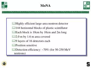
Proposal Technology • Membrane contractor: There are several types of membrane contractor such as: • Hollow Fiber Capillary • Plate and Frame • Spiral Wound • The one that will be used in this project is the hollow fiber membrane due to • the following advantages: • Very small diameter • Large number of membrane • Density
Contaminated Gas Absorbent Liquid
Summary of Achievements in GPI • Material Balance
Stream 7 Stream 6 Stream 8 Summary of Achievements in GPI • Material Balance Regenerator
Summary of Achievements in GPI • Energy Balance stream 8 Lean solvent • Heat Exchanger • Shell-Tube heat exchanger • Q Tube= • Q Shell= stream 6 rich solvent
Summary of Achievements in GPI • Energy Balance Pump: Cooler:
Detailed Design Membrane Contractor V-101 (Num. of tubes , Area) Flash drum V-102 (diameter , height) Regenerator T-101 (diameter , height) Pump P-101 (power required) Heat exchanger E-101 ( Heat Duty, Area, Number of tube )
Membrane Contractor V-101 Data of membrane: The following data was obtained from HYSYS program and experiments Thelargest area should be selected and it was for CO2 Result of Membrane:
Flash drum separator V-102 Data for the flash drum design The following data was obtained from HYSYS program
Flash drum separator V-102 Flash Result:
Regenerator T-101 • For regenerator design two parameters must be calculated the diameter and the height of the tower Data for the regenerator design The Following data was obtained from HYSYS program:
Regenerator T-101 Regenerator Results:
Details of Cost Analysis & Discussion Membrane cost: b) For tubes: Total tube cost = # of tubes • Total tube cost=9,125,455 tubes x 2($/m)*0.14m=$2,555,127 • The total is the summation of the vessel cost and its internals (tubes) cost: • Total Capital Cost =$239,000+$2,555,127=$2,794,127 • Finally, the total Bare Module Cost = $ 3,936,127
Operating Cost Labor cost Required Data: Results:
Codes of Ethics • American Institute of Chemical Engineers (AIChE). • Engineering Ethics: is the field of applied ethics which studies and sets • standards for engineers’ obligations. • Engineers are expected to apply: • Highest standards of honesty and integrity • Fair and work with commitment to other employees • Seeking to complete their job in a good way • Use their knowledge and skill for the enhancement of human welfare
Ethical Dilemmasof Proposed Solution • The biggest issue is faced when the CO2 and H2S are not removed from the flue gas by flash drum . • 2% CO2 and 0.0001% H2S contents in flue gas are considered acceptable • To reduce the percentage of toxic gases • membrane contractor is used to absorb high concentrations of toxic gases • To eliminate leakage of rich DEA : • sensors on the streams • selecting the suitable corrosion resistant materials
Environmental Impact of the Process • H2S & Environment • Separation of H2S depend upon the movement of air currents. • In the atmosphere layer, it’s usually react with other chemicals to be broken down within a period of few days
Environmental Impact of the Process • CO2 & environment • Thermosphere absorb CO2 Release heat as IR and allow more UV. • Troposphere Greenhouse gases trap heat + increase climate T = Global warming • Carbonic acid is corrosive and causes acid rain.
Environmental Impact of the Process • CO2 & environment • Asphyxiation • Frostbite (skin burning) • Bicarbonate (HCO3) causes: • Buffer “pH” system • Kidney damage
Environmental Impact of the Process • DEA & environment • Short-term inhalation exposure to DEA in humans may result : • Irritation of the nose, throat and skin • DEA and related amines may be converted to the corresponding nitrosamine of which is highly carcinogenic • Body and organ weight changes
Hazard and Operability (HAZOP ) HAZOP is a examination of a planned or existing process or operation in order to identify and evaluate problem that may represent the risks to personnel or equipments, or prevent efficient operation. The HAZOP should be carried out after design is complete. It is a final check when the detailed design has been completed
Hazard and Operability (HAZOP ) • Available properties information for process HAZOP should be: • Process flow diagrams • Piping and instrumentation diagrams (P&IDs) • Layout diagrams • Heat and material balances • Equipment data sheets Start-up and emergency shut-down procedures
Problemsfaces and solutions • No data available for DEA such as the solubility • Lack information about the membrane contractor • Some of websites need registration to access it