Understanding Signal Encoding Schemes: Digital Data Conversion Techniques
This article delves into signal encoding, covering analog and digital conversion techniques, types of coding methods, and characteristics of encoding schemes. Topics include signal levels, bit rate, baud rate, DC component, noise immunity, error detection, and synchronization. Line coding techniques like Unipolar NRZ and Polar encoding schemes such as NRZ, RZ, and Biphase NRZ are explored, with details on their characteristics and uses. Learn about digital transmission essentials and essential aspects related to signal encoding schemes.

Understanding Signal Encoding Schemes: Digital Data Conversion Techniques
E N D
Presentation Transcript
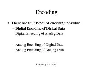
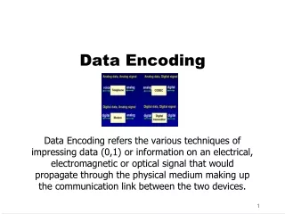
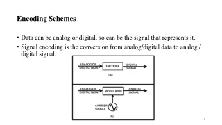
Encoding Schemes • Data can be analog or digital, so can be the signal that represents it. • Signal encoding is the conversion from analog/digital data to analog / digital signal.
Various Conversion techniques used • What type of signal should we used? • It Depends on the situation and available bandwidth.
Digital Data and Digital Signal • Digital Data is converted to digital signal for transmission . • There are three types of coding methods: • Line Coding • Block Coding • Scrambling
Characteristics of Encoding Schemes • No. of signal levels • Bit rate and baud rate • DC component • Signal Spectrum • Noise Immunity • Error Detection • Synchronization • Cost of Implementation
No. of Signal Levels • The Nyquist bit rate formula defines the theoretical maximum bit rate for a noiseless channel • Bitrate = 2 x Bandwidth x Log2 L • Where, • Bitrate is the bitrate of the channel in bits per second • Bandwidth is the bandwidth of the channel • L is the number of signal levels.
Bit rate and Baud rate Bit Rate • It is the number of bits transmitted in one second. • It is expressed as bits per second (bps). Baud Rate • It is the rate of Signal Speed, i.e the rate at which the signal changes. • A digital signal with two levels ‘0‘ & ‘1‘ will have the same baud rate and bit rate. • Baud Rate = Bit Rate / No. of Bits per signal. • In the digital transmission, bit rate should be higher than the baud rate (i.e. lower than the bit rate)
DC Component • The average amplitude of a signal is nonzero. • This creates what is called a direct current (DC) component (a component with zero frequency). • When a signal contains a DC component, it cannot travel through media that cannot handle DC components.
Signal Spectrum • Range of frequencies contained in a signal. Noise Immunity • Noise is defined as an unwanted data. When some electromagnetic signal gets inserted during the transmission, it is generally called as a Noise. Due to Noise it is difficult to retrieve the original data or information. Error Detection • Error Detection uses the concept of redundancy, which means adding extra bits for detecting errors at the destination. Cost of Implementation • To minimize cost of implementation.
Synchronization • In order to receive the signals correctly, the receivers bit intervals must correspond exactly to the senders bit intervals. • The clock frequency of the transmitter and receiver should be the same. • If the clock frequency at the receiver is slower or faster than the bit intervals are not matched and the received signal is different than the transmitted one. • Different Methods to achieve synchronization : A separate line used for clock information, but it very costly due to a separate link increase wire expenditure. • Secondly, Regenerate clock at the receiver end with special hardware (phase lock loop).
Line Coding • Technique for converting digital data into digital signal. • Types of Line Coding
Unipolar NRZ Scheme • Unipolar encoding is very simple and very primitive. • It is almost obsolete today. • All signal levels are either above or below the time axis. • NRZ - Non Return to Zero scheme is an example of this code. • The signal level does not return to zero during a symbol transmission.
Characteristics • It uses only one polarity of voltage level bit rate same as data rate. • Bit rate same as data rate. • DC component present. • Loss of synchronization for long sequences of 0’s and 1’s.
Polar • Uses two voltage levels one positive and the other one negative. • There are three types of polar encoding schemes • NRZ • RZ • Biphase
NRZ • Voltage level is constant during a bit interval. • There are two NRZ schemes • NRZ –L (Non Return Zero-Level) • NRZ-I (Non Return Zero-Inversion) • In NRZ-L the level of the voltage determines the value of the bit. In NRZ-I the inversion or the lack of inversion determines the value of the bit. • In NRZ-L, 1’s is the low level and 0’s is the high level. • In NRZ-I, for each 1 in the bit sequence, the signal level is inverted. • A transition from one voltage level to the other represents a 1.
Characteristics • Two levels • Bit rate same as data rate. • Loss of synchronization for long sequences of 0’s or 1’s. • Most of the energy is concentrated between 0 and half the bit rate. • No DC component.
RZ (Return Zero) • Three values : Positive, Negative and Zero • To ensure synchronization there must be a signal transition in each bit. • For 0, transition low to middle of zero • For 1, transition high to middle of zero.
Characteristics • Three Levels • Bit rate is double that of data rate. • No DC component • Good Synchronization • Increase in bandwidth is the main limitation.
Biphase Encoding • There are two types of biphase encoding schemes • Manchester • Differential Manchester
Manchester Encoding • In Manchester code the mid bit transition serves as a clocking mechanism and also as data. • Low to high represents a 1. • High to low represents a 0.
Differential Manchester • Presence of transition in the beginning of a bit represent a 0. • Uses inversion in the middle of each bit for synchronization.
Characteristics • Two levels • No DC components • Good Synchronization • Higher bandwidth due to doubling of bit rate with respect to data rate.
Bipolar Encoding • There are two types of bipolar encoding • AMI (Amplitude Mark Inversion) • Pseudo ternary
AMI • AMI encoding schemes idea comes from telephone communication. • Bipolar AMI uses three voltage levels. • Unlike RZ, the zero level is used to represent a 0. • Binary 1’s are represented by alternating positive and negative voltages.
Pseudo ternary • Same as AMI, but alternating positive and negative pulses occurs for binary 0 instead of binary 1. Characteristics • Three Levels • No DC components • Loss of synchronization for long sequences of 0’s and 1’s. • Lesser bandwidth
Scrambling Schemes • Extension of Bipolar AMI • Used in case of long distance applications because for short distance, bandwidth is not important for transmission. Goals • No DC components • No long sequences of 0 level line signal • No increase in bandwidth • Error detection capability • Examples : B8ZS, HDB3
B8ZS (Bipolar with 8 zero substitution) • The Limitation of bipolar AMI is overcome in B8Zs. Commonly used in North America, Eight consecutive zero level voltages are replaces by the sequence • A sequence of eight 0’s is replaced by 000+-0-+, if the previous pulses was positive • A sequence of eight 0’s is replaced by 000-+0+-, if the previous pulses was negative
HDB3 (High Density bipolar 3 zero) • Another alternative, which is used in Europe and Japan • It Replaces a sequence of 4 zeros by a code as per the rule given in the below table
Characteristics • Three Levels • No DC components • Good Synchronization • Well Suited for long distance transmission over long distance.
Analog data to Analog Signal • The Process of converting analog data to analog signal is called Modulation. • Modulation is used to send an information bearing signal over long distances. • Modulation is the process of varying some characteristic of a periodic wave with an external signal called carrier signal. • These carrier signals are high frequency signals and can be transmitted over the air easily and are capable of traveling long distances.
The characteristics (amplitude, frequency, or phase) of the carrier signal are varied in accordance with the information bearing signal(analog data). • The information bearing signal is also known as the modulating signal. • The modulating signal is a slowly varying – as opposed to the rapidly varying carrier frequency.
Need of Modulation • Frequency translation: Modulation translates the signal from one region of frequency domain to another region. This helps to transmit the modulated signal with minimum attenuation through a particular medium. • Multiplexing: Different base band signals originating from different sources can be translated to different frequency ranges. This allows transmission of different signals through the same medium using frequency division multiplexing (FDM)
Practical size of antenna: Modulation translates baseband signal to higher frequency, which can be transmitted through a bandpass channel using an antenna of smaller size. This has made communication practical. Suppose we transmitted 3KHz, what is the height of antenna This height is impractical, So we modulates this signal, Now the modulating signal is 300MHz This height is easily practical
Narrowbanding: As modulation translates a signal from lower frequency domain to higher frequency domain, the ratio between highest to lowest frequency of the modulated signal becomes close to 1. Suppose we transmitted 20 Hz (lowest frequency) and 20 KHz (highest frequency) Narrowbanding ratio= highest freq/lowest freq = 1000 Now, we modulate these signals with 1MHz Narrowbanding ratio=1.002
Amplitude Modulation (AM) • Amplitude modulation is a type of modulation where the amplitude of the carrier signal is varied in accordance with modulating signal. • The envelope, or boundary, of the amplitude modulated signal embeds modulating signal. • Amplitude Modulation is abbreviated AM.
The total bandwidth required for AM can be determined from the bandwidth of the audio signal: BAM = 2B.
Frequency Modulation • Frequency modulation is a type of modulation where the frequency of the carrier is varied in accordance with the modulating signal. The amplitude of the carrier remains constant. • The information-bearing signal (the modulating signal) changes the instantaneous frequency of the carrier. Since the amplitude is kept constant, FM modulation is a low-noise process and provides a high quality modulation technique which is used for music and speech in hi- fidelity broadcasts. • Frequency Modulation is abbreviated FM.
The total bandwidth required for FM can be determined from the bandwidth of the audio signal: BFM = 10B.
Phase Modulation • In phase modulation, the instantaneous phase of a carrier wave is varied from its reference value by an amount proportional to the instantaneous amplitude of the modulating signal. • Phase Modulation is abbreviated PM.
The total bandwidth required for PM can be determined from the bandwidth and maximum amplitude of the modulating signal:BPM = 10B.
Transmission Media • A transmission medium can be broadly defined as anything that can carry information from a source to a destination. • For example, the transmission medium for two people having a dinner conversation is the air. The air can also be used to convey the message in a smoke signal. For a written message, the transmission medium might be a mail carrier.
Guided Media • Guided media, which are those that provide a conduit from one device to another, include twisted-pair cable, coaxial cable, and fiber-optic cable. • A signal traveling along any of these media is directed and contained by the physical limits of the medium. • Twisted-pair and coaxial cable use metallic (copper) conductors that accept and transport signals in the form of electric current. • Optical fiber is a cable that accepts and transports signals in the form of light.
Twisted Pair Cable • Frequency range for twisted pair cable is 100 Hz to 5MHz. • A twisted pair consists of two conductors (normally copper), each with its own plastic insulation, twisted together, • One of the wires is used to carry signals to the receiver, and the other is used only as a ground reference. • The receiver uses the difference between the two. • In addition to the signal sent by the sender on one of the wires, interference (noise) and crosstalk may affect both wires and create unwanted signals. • If the two wires are parallel, the effect of these unwanted signals is not the same in both wires because they are at different locations relative
to the noise or crosstalk sources (e,g., one is closer and the other is farther). This results in a difference at the receiver. • By twisting the pairs, a balance is maintained. For example, suppose in one twist, one wire is closer to the noise source and the other is farther; in the next twist, the reverse is true. • Twisting makes it probable that both wires are equally affected by external influences (noise or crosstalk). • This means that the receiver, which calculates the difference between the two, receives no unwanted signals. The unwanted signals are mostly canceled out. • Twisted pair cable comes in two forms : unshielded and shielded
Unshielded Versus Shielded Twisted-Pair Cable • The most common twisted-pair cable used in communications is referred to as unshielded twisted-pair (UTP). • IBM has also produced a version of twisted-pair cable for its use called shielded twisted-pair (STP). • STP cable has a metal foil or braided- mesh covering that encases each pair of insulated conductors. • Although metal casing improves the quality of cable by preventing the penetration of noise or crosstalk, it is bulkier and more expensive. • The Electronic Industries Association (EIA) has developed standards to classify unshielded twisted-pair cable into seven categories.
Categories are determined by cable quality, with 1 as the lowest and 7 as the highest. • The most common UTP connector is RJ45 (RJ stands for registered jack)