Communication Cables
Communication Cables. Teltec, Uganda. History of Cables:.

Communication Cables
E N D
Presentation Transcript
Communication Cables Teltec, Uganda Teltec, Uganda
History of Cables: • The earliest use of cables was in Telegraphy lines. The cables were termed as SWER (Single Wire Earth Return) circuits, Figure 3. These are single phase lines (un-insulated), that were used in Single Wire Transmission. The use of this form of communication soon started having interference (noise) from the Trams (Electric Trains) and other electricity-using devices. • After this, companies converted to Balanced circuits lines. These are implemented using two wires which have circuits installed at every distance, or at the receiving or transmitting end, that cancel out the interference. See figures 5,6, and 7. • Secondly, since the they are two wires, on transmitting and the other receiving, the interference in the two lines is canceled out automatically. • Balanced lines increase length by decreasing the signal attenuation. • Since most of the telephone lines were installed next to power lines, this caused the interference that is induced from the power lines, and with the advancement of power, the interference kept on increasing. • This brought in a new era of the wire transposition, Figure 4 in a bid to reduce on the interference induced into the cables. In wire transposition, the transmit and receive cables change position every 6 to 7 poles (around 4 twists every Kilometer). The change in position helps to increase interference cancelation. • The wire transposition was not enough in the reduction of noise in the communication lines. This led to the introduction of twisted pair cables. Teltec, Uganda
Figure 6- Balancing with capacitor and inductors Figure 4- Wire Transposition Figure 3- SWER Figure 5- Balancing with Transformers Figure 7- Balancing with Op Amps Teltec, Uganda
Fig. 1. Balanced line in twisted pair format. This line is intended for use with 2-wire circuits. Fig. 2. Balanced line in star quad format. This line is intended for use with 4-wire circuits or two 2-wire circuits. It is also used with microphone signals in professional radio. Fig. 3. Balanced line in DM quad format. This line is intended for use with 4-wire circuits or two 2-wire circuits. Teltec, Uganda
Fig. 4. Balanced line in twin lead format. This line is intended for use with RF circuits, particularly antennas. The twisted pair cables aim at cancelling EMI (Electromagnetic Interference) from all neighboring cables. Teltec, Uganda
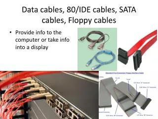
Computer Networking History: 10BASE5 The earliest form networking was done by coaxial cables, implementing 10Mbps using the RG-8X type (expensive) of coaxial cable. To add a computer to the network was simple as drilling into the cable to its core and connecting a coaxial cable to the core. 10BASE2 In the next generation of networking, a 50Ω RG-58 coaxial cable (cheap) was used. This remained a dominant networking method for a long, with a network speed of 10Mbps. To connect another computer to the network, a T-connector BNC was used. 1BASE5 Then came first use of the twisted pair but accomplishing connection speeds of 1Mbps, with a hub. This kind of networking never went commercial. 10BASE‑T The next generation was the 10Base-T which was running over four wires (2 twisted pairs) on a Category 3 or 5. An active hub or switch sits in the centre of the network and has a port for each node. This is same configuration that was used in the 100Base-T. FOIRL The next generation is the fiber-optic inter-repeater link (FOIRL). This is the original standard for Ethernet over fiber. Teltec, Uganda
Cable Overview – Based on Applications. • E1 • Ethernet (Cat 5, 5e and 6) • Coaxial Cables (un-balanced line) • Fiber • Waveguide Teltec, Uganda
E1/ T1 Cables: Figure 1: The cable shown in the figure is an 8E1 cable. Depending on the Size of the Cable, it can carry from 8 to 32 E1s/T1s, each E1 being made up of 4 twisted cables. Each pair of cables is twisted onto each other to achieve noise cancellation. The cable shown in figure 1 is a Cisco Cable. For more information of how its used, read thru the mvcbl.pdf. Please note that E1s can also be achieved using the an RJ 45 Connector, as shown in figure 2. The figure shows the implementation of 2 E1 using Cat 5 cable and RJ 45 Connectors. Teltec, Uganda
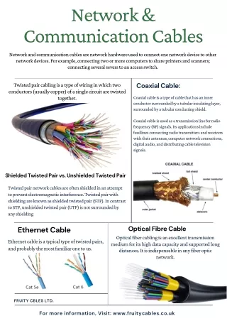
Figure 2: Ethernet Cables: These are the cables that are mainly used in computer networking, in LANs (Local Area Networks). Teltec, Uganda
Ethernet Cables (3, 5, and 6) Introduction: Ethernet cables are used mainly in LANs. It should be noted that in all these cables, the same kind of connector is used, RJ45. Its the type of cable that differs. Cat 3: Commonly known as Category 3, is a UTP (Unshielded twisted pair), designed to reliably carry 10Mbps at the bandwidth 16MHz. This type of cable was common in the early 1990s’, but its popularity fell to a more faster and more reliable cable, Cat 5. Cat 5: Category 5 is a twisted pair cable with a high signal integrity. Its designed to be used in both Ethernet and ATM applications. Its also used to carry other types of information, ie Telephony and video. Most the Cat 5 cables are unshielded relying to the twisted nature for noise rejection. Mainly used for 100Mbps.To view the other specs for 5, 5e, and 6, please look thru the document specs.pdf. Cat 6: Also known as category 6, its mainly used for Gigabit Ethernet and is also compatible to cat 3, 5, 5e. For more details, please look thru the document specs.pdf. Teltec, Uganda
Coaxial Cables: Coaxial cables provide the simplest and most versatile method for transmission of RF and microwave energy. The common types consist of a cylindrical metallic inner conductor surrounded by a dielectric material and then enclosed by a cylindrical metallic outer conductor. The dielectric material is used to maintain the inner conductor concentrically within the outer conductor. The dielectric material is typically polyethylene (PE), Polyproplene (PP) or tetraflouroethylene (TFE). Most coaxial cables are then coated with a protective jacket made of polyethylene or poly-vinyl chloride (PVC). General Applications: Short interconnections between RF electronic equipment Usually this application is inside buildings, and in equipment racks, these cables, traditionally, have been called RF cables. They are usually 0.5 in or smaller in diameter and use solid insulating material. The outer conductor is usually copper or aluminum braid and the insulating material is solid. The conductor is copper or copper clad steel. The advantage with these cables is that they are inexpensive and very to handle in terms of weight and flexibility. For more information about these coax cables, look thru the attached document Coax Cable Specifications: Teltec, Uganda
Coaxial Cables Continued….. Connectors. The connectors of these coaxial cables are either of a bayonet style coupling for ease of assembly or a screw-type coupling for better protection from moisture. The BNC connector, a bayonet style is used extensively with test equipment when the cables need to be removed and reattached numerous number of times during testing. For more information about these coax cables, look thru the attached document Coax Cable connector Specifications: Longer connections between the signal source and its antenna For interconnection between a source and its antenna. The cable may be several feet long and experience extreme environmental conditions. For high power broadcast stations, the use of rigid coaxial transmission lines is very common. Semi flexible use solid outer conductors that are fabricated form copper strips that have been seam welded into continuous cylinders. For flexibility, the outers are corrugated to permit bending to account for thermal expansion when exposed to various temperatures. Solid foam dielectric materials or spiral wound dielectric spacer is used to maintain the concentricity between the inner and outer conductors. For even higher power higher power handling and lower attenuation rigid coaxial transmission line can be used. These can range from 3 1/8 in diameter to 8 3/16, mainly used in FM and TV transmission. Rigid coaxial transmission lines table. Teltec, Uganda
Please view the attached documents for LDF5-50A, LDF7-50A, HJ5-50, HJ7-50A, HJ8-50B, HJ11-50, HJ9-50 cables and their connectors. Teltec, Uganda
Fiber: An optical fiber or optical fiber is a thin, flexible, transparent fiber that acts as a waveguide, or "light pipe", to transmit light between the two ends of the fiber. Optical fibers are widely used in fiber-optic communications, which permits transmission over longer distances and at higher bandwidths (data rates) than other forms of communication. Fibers are used instead of metal wires because signals travel along them with less loss and are also immune to electromagnetic interference. Fibers are also used for illumination, and are wrapped in bundles so they can be used to carry images, thus allowing viewing in tight spaces. Specially designed fibers are used for a variety of other applications, including sensors and fiber lasers. Optical fiber typically consists of a transparent core surrounded by a transparent cladding material with a lower index of refraction. Light is kept in the core by total internal reflection. This causes the fiber to act as a waveguide. Types of Fibers: Multi-Mode Fibers (MMF):Figure A, Slide 18, Also Figure B, Slide 18 These are fibers that can support many propagation paths or transverse modes. Fiber with large core diameter (greater than 10 micrometers) is called multi-mode fiber. In a step-index multi-mode fiber, rays of light are guided along the fiber core by total internal reflection. Teltec, Uganda
Fiber: Continued.... Rays that meet the core-cladding boundary at a high angle (measured relative to a line normal to the boundary), greater than the critical angle for this boundary, are completely reflected. The critical angle (minimum angle for total internal reflection) is determined by the difference in index of refraction between the core and cladding materials. Rays that meet the boundary at a low angle are refracted from the core into the cladding, and do not convey light and hence information along the fiber. The critical angle determines the acceptance angle of the fiber. In graded-index fiber, the index of refraction in the core decreases continuously between the axis and the cladding. This causes light rays to bend smoothly as they approach the cladding, rather than reflecting abruptly from the core-cladding boundary. The resulting curved paths reduce multi-path dispersion because high angle rays pass more through the lower-index periphery of the core, rather than the high-index center. The index profile is chosen to minimize the difference in axial propagation speeds of the various rays in the fiber. This ideal index profile is very close to a parabolic relationship between the index and the distance from the axis. Single-Mode Fibers (SMF): See figure B, Slide 18. The waveguide analysis shows that the light energy in the fiber is not completely confined in the core. Instead, especially in single-mode fibers, a significant fraction of the energy in the bound mode travels in the cladding as an evanescent wave. Teltec, Uganda
Single Fiber Mode Continued..... The most common type of single-mode fiber has a core diameter of 8–10 micrometers and is designed for use in the near infrared. The mode structure depends on the wavelength of the light used, so that this fiber actually supports a small number of additional modes at visible wavelengths. Multi-mode fiber, by comparison, is manufactured with core diameters as small as 50 micrometers and as large as hundreds of micrometers. Materials: Glass optical fibers are almost always made from silica, but some other materials, such as fluorozirconate, fluoroaluminate, and chalcogenide glasses as well as crystalline materials like sapphire, are used for longer-wavelength infrared or other specialized applications. Silica and fluoride glasses usually have refractive indices of about 1.5, but some materials such as the chalcogenides can have indices as high as 3. Typically the index difference between core and cladding is less than one percent. Plastic optical fibers (POF) are commonly step-index multi-mode fibers with a core diameter of 0.5 millimeters or larger. POF typically have higher attenuation coefficients than glass fibers, 1 dB/m or higher. Teltec, Uganda
Practical Situations: In practical fibers, the cladding is usually coated with a tough resin buffer layer, which may be further surrounded by a jacket layer, usually glass. These layers add strength to the fiber but do not contribute to its optical wave guide properties. Rigid fiber assemblies sometimes put light-absorbing ("dark") glass between the fibers, to prevent light that leaks out of one fiber from entering another. This reduces cross-talk between the fibers, or reduces flare in fiber bundle imaging applications. Modern cables come in a wide variety of sheathings and armor, designed for applications such as direct burial in trenches, high voltage isolation, dual use as power lines, installation in conduit, lashing to aerial telephone poles, submarine installation, and insertion in paved streets. Fiber cable can be very flexible, but traditional fiber's loss increases greatly if the fiber is bent with a radius smaller than around 30 mm. This creates a problem when the cable is bent around corners or wound around a spool. "Bendable fibers", targeted towards easier installation in home environments, have been standardized as ITU-T G.657. This type of fiber can be bent with a radius as low as 7.5 mm without adverse impact. Another important feature of cable is cable withstanding against the horizontally applied force. It is technically called max tensile strength defining how much force can applied to the cable during the installation period. Teltec, Uganda
Practical Situations: Continued.... Telecom Anatolia fiber optic cable versions are reinforced with aramid yarns or glass yarns as intermediary strength member. In commercial terms, usage of the glass yarns are more cost effective while no loss in mechanical durability of the cable. Glass yarns also protect the cable core against rodents and termites Figures: Figure B: Fiber Types Figure A: Multi-Mode Fiber Figure C: Fiber Cable Assembly Teltec, Uganda
Termination and splicing Optical fibers are connected to terminal equipment by optical fiber connectors. These connectors are usually of a standard type such as FC, SC, ST, LC, or MTRJ. Insert document about the types of connectors Optical fibers may be connected to each other by connectors or by splicing, that is, joining two fibers together to form a continuous optical waveguide. The generally accepted splicing method is arc fusion splicing, which melts the fiber ends together with an electric arc. For quicker fastening jobs, a "mechanical splice" is used. Fusion splicing is done with a specialized instrument that typically operates as follows: The two cable ends are fastened inside a splice enclosure that will protect the splices, and the fiber ends are stripped of their protective polymer coating (as well as the more sturdy outer jacket, if present). The ends are cleaved (cut) with a precision cleaver to make them perpendicular, and are placed into special holders in the splicer. The splice is usually inspected via a magnified viewing screen to check the cleaves before and after the splice. The splicer uses small motors to align the end faces together, and emits a small spark between electrodes at the gap to burn off dust and moisture. Teltec, Uganda
Termination and Splicing Continued…… Fibers are terminated in connectors so that the fiber end is held at the end face precisely and securely. A fiber-optic connector is basically a rigid cylindrical barrel surrounded by a sleeve that holds the barrel in its mating socket. The mating mechanism can be "push and click", "turn and latch" ("bayonet"), or screw-in (threaded). A typical connector is installed by preparing the fiber end and inserting it into the rear of the connector body. Quick-set adhesive is usually used so the fiber is held securely, and a strain relief is secured to the rear. Once the adhesive has set, the fiber's end is polished to a mirror finish. Various polish profiles are used, depending on the type of fiber and the application. For single-mode fiber, the fiber ends are typically polished with a slight curvature, such that when the connectors are mated the fibers touch only at their cores. This is known as a "physical contact" (PC) polish. The curved surface may be polished at an angle, to make an "angled physical contact" (APC) connection. Such connections have higher loss than PC connections, but greatly reduced back reflection, because light that reflects from the angled surface leaks out of the fiber core; the resulting loss in signal strength is known as gap loss. APC fiber ends have low back reflection even when disconnected. Teltec, Uganda
Waveguides: In electromagnetics and communications engineering, the term waveguide may refer to any linear structure that conveys electromagnetic waves between its endpoints. However, the original and most common meaning is a hollow metal pipe used to carry radio waves. This type of waveguide is used as a transmission line mostly at microwave frequencies, for such purposes as connecting microwave transmitters and receivers to their antennas, in equipment such as microwave ovens, radar sets, satellite communications, and microwave radio links. A dielectric waveguide employs a solid dielectric rod rather than a hollow pipe. An optical fiber is a dielectric guide designed to work at optical frequencies. Transmission lines such as microstrip, coplanar waveguide, stripline or coaxial may also be considered to be waveguides. The electromagnetic waves in (metal-pipe) waveguide may be imagined as travelling down the guide in a zig-zag path, being repeatedly reflected between opposite walls of the guide. For the particular case of rectangular waveguide, it is possible to base an exact analysis on this view. Propagation in dielectric waveguide may be viewed in the same way, with the waves confined to the dielectric by total internal reflection at its surface. Some structures, such as Non-radiative dielectric waveguide and the Goubau line, use both metal walls and dielectric surfaces to confine the wave. Teltec, Uganda
Types of waveguides: • - Rectangular waveguide: This is the most commonly used form of waveguide and has a rectangular cross section. • - Circular waveguide: Circular waveguide is less common than rectangular waveguide. They have many similarities in their basic approach, although signals often use a different mode of propagation. • - Circuit board stripline: This form of waveguide is used on printed circuit boards as a transmission line for microwave signals. It typically consists of a line of a given thickness above an earth plane. Its thickness defines the impedance. • Uses: • Optical fibers applications • In microwave, a waveguide guides microwaves from a magnetron were waves are formed. • In radar applications • Stripline – Waveguides for printed circuit boards. • Note: For more information about waveguides and the related frequency application, please view the document Waveguide Specs Teltec, Uganda
Sample Waveguides: Rectangular Waveguide Teltec, Uganda
End Thank you Teltec, Uganda