Download
1 / 39

E N D
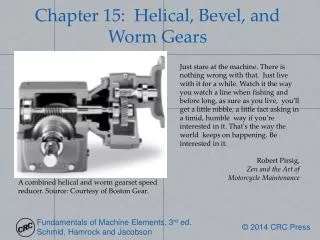
Just stare at the machine. There is nothing wrong with that. Just live with it for a while. Watch it the way you watch a line when fishing and before long, as sure as you live, you'll get a little nibble, a little fact asking in a timid, humble way if you're interested in it. That's the way the world keeps on happening. Be interested in it. Robert Pirsig, Zen and the Art of Motorcycle Maintenance Chapter 15: Helical, Bevel, and Worm Gears A combined helical and worm gearset speed reducer. Source: Courtesy of Boston Gear.
Helical Gear Figure 15.1: Helical gear. (a) Illustration of meshing helical gears; (b) front view; (c) side view.
Gear Design Considerations Table 15.1: Design considerations for gears.
Helical Gear Pitches Figure 15.2: Pitches of helical gears. (a) Circular; (b) axial.
AGMA Equations for Helical Gears Correction factors are determined as in Chapter 14, except for geometry factor. This can be approximated from
Helical Gear Geometry Factor Figure 15.3: Helical gear geometry factor as a function of helix angle when mating with a 75-tooth gear. Source:Courtesy of the American Gear Manufacturers Association.
Correction Factor vs. Helix Angle Figure 15.4: Helical gear geometry correction factor as a function of helix angle. Source:Courtesy of the American Gear Manufacturers Association.
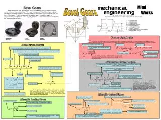
Types of Bevel Gears Figure 15.5: Types of bevel gears; (a) a straight bevel gear set; (b) a Zerol gear set; (c) spiral bevel gear set; (d) hypoid bevel gear set. Source:Courtesy of ATI Precision Gearing.
Bevel Gear Terminology Figure 15.6: Terminology for bevel gears.
Gear Mounting Figure 15.7: Schematic illustration of the two basic forms of gear mounting. (a) Straddle mounting, where the gear is located between bearings; (b) overhang mounting. Note that deep groove rolling element bearings are shown, but often a bearing better suited for thrust load support is required in at least one location.
Bevel Gear Forces Straight bevel gears: Spiral bevel gears: where the ± refers to different rotation directions or spiral direction. Figure 15.8: Forces acting on a bevel gear.
AGMA Equations for Bevel Gears Ko and Kv are defined as for spur gears. The load distribution factor is: The crowning factor is, for contact stress: And for bending:
Size Factor Figure 15.9: Size factor for bevel gears. (a) Size factor for bending stress; (b) size factor for contact stress or pitting resistance. Source:From AGMA [2010].
Geometry Factor for Contact Stress (Straight Bevel Gears) Figure 15.10: Geometry factors for straight bevel gears, with pressure angle ϕ=20° and shaft angle = 90°. (a) Geometry factor for contact stress Ib. Source:From AGMA [2010].
Geometry Factor for Bending(Straight Bevel Gears) Figure 15.10: Geometry factors for straight bevel gears, with pressure angle ϕ=20° and shaft angle = 90°. (b) geometry factor for bending Yb. Source:From AGMA [2010].
Geometry Factor for Contact Stress (SpiralBevel Gears) Figure 15.11: Geometry factors for spiral bevel gears, with pressure angle ϕ=20°, spiral angle ψ= 25° and shaft angle = 90°. (a) Geometry factor for contact stress Ib. Source:From AGMA [2010].
Geometry Factor for Bending Stress (Straight Bevel Gears) Figure 15.11: Geometry factors for spiral bevel gears, with pressure angle ϕ=20°, spiral angle ψ= 25° and shaft angle = 90°. (b) geometry factor for bending Yb. Source:From AGMA [2010].
Geometry Factor for Contact Stress (Zerol Bevel Gears) Figure 15.12: Geometry factors for Zerol bevel gears, with pressure angle ϕ=20°, spiral angle ψ= 25°and shaft angle = 90°. (a) Geometry factor for contact stress Ib. Source:From AGMA [2010].
Geometry Factor for Bending Stress (Zerol Bevel Gears) Figure 15.12: Geometry factors for Zerol bevel gears, with pressure angle ϕ=20°, spiral angle ψ= 25°and shaft angle = 90°. (b) geometry factor for bending Yb. Source:From AGMA [2010].
Design Procedure 15.1: Bevel Gear Synthesis This design procedure will assist in the selection of preliminary bevel gear geometries where the application's load, speed, and desired gear ratios are known. The discussion will be limited to spiral bevel gears. The approach is also restricted to 90°shaft angles. An estimate for the required pinion diameter can be obtained from the pinion torque and gear ratio using Fig.15.14 for surface pitting and Fig.15.13 for bending strength. For precision finished gears (which have a cost penalty), the pinion diameter from pitting resistance can be multiplied by 0.80. From the two pinion diameter estimates, the larger value should be selected for further evaluation. The pinion diameter selected in Step 1 is based on using case hardened steel with a hardness of 55 HRC, and other materials will require a modification in the pinion diameter. Table 15.2 lists material modification factors for selected materials. An updated pinion diameter can be obtained by multiplying the estimate obtained from Step 1 by the materials factor from Table 15.2.
Design Procedure 15.1 (continued) Figure 15.15 provides an estimate for the number of teeth that should be machined into the pinion. Spiral bevel gears can maintain a higher contact ratio than straight or Zerol bevel gears, so departure from the recommendation in Fig.15.15 is not uncommon. Also, note that Fig.15.15 is for a 35°spiral angle, so that a high contact ratio can be preserved for fewer teeth (see Step 6). The outer transverse diametral pitch, pdo, can be obtained from Eq. (14.5) as the ratio of the number of teeth in the pinion to the pinion diameter. The face width of the spiral bevel gear can be obtained from Fig.15.16 as a function of pinion pitch diameter and gear ratio. The face width should not exceed 10/pdo, however.
Design Procedure 15.1 (continued) • The spiral angle should be selected based on a face contact ratio of 2.0. AGMA [2003] recommends higher values for smooth and quiet operation, or high speed applications. Face contact ratios below 2.0 can be tolerated for some applications, but this is a reasonable value for preliminary design synthesis. The face contact ratio is given by • so that • where\ • Ao = outer cone distance (see Fig.15.6). • Am = mean cone distance • pdo = other transverse diametralpitch • bw = net face width • ψ = mean spiral angle at the pitch surface.
Design Procedure 15.1 (concluded) The most common pressure angle for bevel gears is 20°, and is recommended for initial design synthesis. However, higher or lower pressure angles can be used. Lower pressure angles increase the contact ratio, reduce axial and separating forces, and increase the tooth slot widths. However, lower pressure angles increase the risk of undercut gear teeth and associated high stress concentrations. The results from this Design Procedure generally are a reasonable starting point for gear design. As is usually the case, results from this approach must be modified slightly to produce a useful result. For example, if Fig. 15.15 suggests 32.2 teeth should be used, clearly one should specify 32 or 33 teeth. Also, it is good practice to use blanks that are of standard size, etc.
Pinion Diameter vs. Torque Figure 15.17: Estimated pinion pitch diameter as a function of pinion torque for a number of gear ratios, and based on pitting resistance. Source:From AGMA [2003].
Materials Factor Table 15.2: Material factor for pinion diameter estimate for selected gearset materials. Source:From AGMA [2003].
Pinion Pitch Diameter vs. Torque Figure 15.18: Estimated pinion pitch diameter as a function of pinion torque for a number of gear ratios, and based on bending strength. Source:From AGMA [2003].
Number of Teeth vs. Pinion Pitch Diameter Figure 15.19: Approximate number of teeth for a spiral bevel gear as a function of pinion pitch diameter for various gear ratios. Source:From AGMA [2003].
Spiral Bevel Gear Face Width Figure 15.20: Face width of spiral bevel gears operating at a 90° shaft angle. Source:From AGMA [2003].
Number of Wormgear Teeth Table 15.3: Suggested minimum number of wormgear teeth for customary designs. Source:From ANSI/AGMA [1993].
Worm Gear Contact Figure 15.21: Illustration of worm contact with a worm gear, showing multiple teeth in contact.
Worm Forces Figure 15.22: Forces acting on a worm. (a) Side view, showing forces acting on worm and worm gear. (b) Three-dimensional view of worm, showing worm forces. The worm gear has been removed for clarity.
AGMA Equations for Wormgears Input power rating: where See the text for Cm and Cv. Wf is given by: and
Materials Factor Table 15.4: Materials factor, Cs, for bronze worm gears with the worm having surface hardness of 58 HRC. Source:From AGMA [2010a]
Materials Parameter Figure 15.23: Materials parameter Csfor bronze worm gears and worm minimum surface hardness of 58 HRC. (a) Materials factor for center distances cdgreater than 76 mm (3 in.); (b) Materials factor for center distances cdless than 76 mm (3 in.). When using part (b), the value from part (a) should be checked, and the lower value used. See also Table 15.4. Source:From AGMA [2010a].
Design Procedure 15.2: Worm Gear Synthesis The approach is restricted to coarse pitch cylindrical worm gears operated at right angles. It is recognized that high power transmission at high speeds will require fine-pitch teeth. It is assumed that the worm and worm gear speeds are known, as is the input power. A pressure angle needs to be selected based on the design application. Higher pressure angles lead to higher tooth strength, but have the drawback of higher bearing reaction loads and worm bending stress, as well as resulting in fewer teeth in contact. Lower pressure angles are better suited for high speed and quiet operation. Table 15.3 lists the customary pressure angles for worm gears. The minimum number of teeth in the worm gear is given in Table 15.3. More teeth can be selected if the center distance is not a design constraint. The number of teeth in the worm is then obtained from Eq. (15.36).
Design Procedure 15.2(continued) • The worm pitch diameter usually falls between the following ranges: • Where cdis the the center distance between the axes of the worm and worm gear. • The worm gear pitch diameter is calculated as • The axial pitch of the worm gear is
Design Procedure 15.2 (continued) • Fig.15.20 illustrates the required face width of the worm, which is given as • A slightly larger face width should be used to allow for manufacturing and assembly tolerances. However, most worm gears have between two and three teeth in contact at all times, so using bww= 5pxgives a reasonable face width, allowing an extra axial pitch before and after contact. • If px ≥ 0.160 in. ~ (4.06 mm), the worm gear face width can be determined from • and if px< 0.160 in. ~ (4.06 mm),
Worm Face Width Figure 15.24: Worm face width.
Mixer Gears Figure 15.26: Torque and speed of motor as a function of current for the industrial mixer used in the case study. Figure 15.25: The gears used to transmit power from an electric motor to the agitators of a commercial mixer. Source:Courtesy of Hobart, Inc.