Download
1 / 15
160 likes | 332 Views
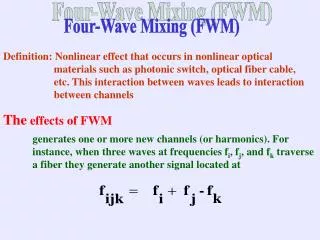
Four-Wave Mixing (FWM). Definition: Nonlinear effect that occurs in nonlinear optical materials such as photonic switch, optical fiber cable, etc. This interaction between waves leads to interaction between channels. The effects of FWM.

E N D
Four-Wave Mixing (FWM) Definition: Nonlinear effect that occurs in nonlinear optical materials such as photonic switch, optical fiber cable, etc. This interaction between waves leads to interaction between channels The effects of FWM generates one or more new channels (or harmonics). For instance, when three waves at frequencies fi, fj, and fk traverse a fiber they generate another signal located at
Fiber Example : The input is two signals located at 1 and 2 traverse a fiber of length (L) and the output is four different signals located at 1, 2, 21 - 2, and 22 - 1 .
In general the number of newly generated signals is given by
The power of of newly generated signals is given by Where Pi , Pj , Pk are the input power of the channels D is the degeneracy factor 3 and 6 for two-tone and 6 for three-tone product And is given by Where Aeff is the effective cross-sectional area and Leff is the effective length of the fiber given by
The nonlinear susceptibility1111 The efficiency η is given by Where fmn = fm - fn, (m,n = 1, 2, 3)
Table 3.xxxxxx: Fiber parameters. The following figure demonestrate the effect of FWM when Four signals with equally power 3mw traverses a fiber with the following specifications Description Values Attenuation factor () 0.2 dB/km Effective fiber cross-sectional area ( Aeff ) 6.4x10⁻¹¹m2 Third order nonlinear susceptibility (1111) 6*10-15 cm3/erg Chromatic dispersion (Dc) 1ps/nm.km Dispersion slope ( ) .07ps/km.nm2 Refractive-index (n) 1.48 Length L 75 km Wavelength ( ) 1550 nm
The newly generated signals and their corresponding power in dBm
The newly generated signals and their corresponding power in dBm after filtration
The original and the newly generated signals after filtration as well as their corresponding power in dBm
Noise Contributions in Optical Systems and detection I. Thermal Noise: K is Boltzmann’s constant, T is the absolute temperature in Kelven, B is the receiver electrical bandwidth and R is the load resistance value. II. Shot Noise Where q is the electronic charge, I is the mean optically generated current and Id is the photo detector dark current III. Relative Intensity Noise (RIN):
The Optical Signal- to- Noise Ratio (OSNR) is given by [Reference] Where is given by The noise due to FWM phenomenon is given by [Reference]
Now, the question coming at this juncture how to include the effect of FWM in the fiber metrics • Based on the system design target, which is mainly the BER, Q (or OSNR) can be evaluated from the BER curve. • The noise in the system can also be calculated (mainly Nth , Nsh , and NFWM). • From step I and II, the required received power (Prec) thus can be calculated. • Using the Power budget equation, the maximum fiber length ( Lmax in km) can be calculated as follow