Download
1 / 63
630 likes | 743 Views
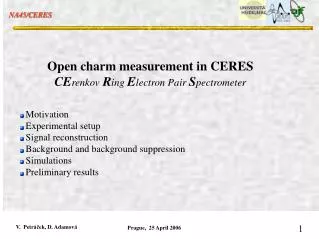
Open charm measurement in CERES CE renkov R ing E lectron Pair S pectrometer. Motivation Experimental setup Signal reconstruction Background and background suppression Simulations Preliminary results. Motivation I. Charm quark mostly produced from the initial fusion of partons

E N D
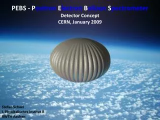
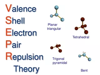
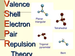
Open charm measurement in CERES CErenkov RingElectronPairSpectrometer Motivation Experimental setup Signal reconstruction Background and background suppression Simulations Preliminary results
Motivation I Charm quark mostly produced from the initial fusion of partons (mostly gluons) Open charm production sensitive to initial parton distribution functions 2001, Dokshitzer and Kharzeev proposed “dead cone” effect => charm quark small energy loss, but in vacuum Recent: Heavy quark energy loss in medium, e.g.: Armesto et al, PRD 71, 054027, 2005; M. Djordjevic et al., PRL 94, 112301, 2005. Z. Lin & M. Gyulassy, PRC 51 (1995) 2177 light 3
Motivation II Charmed quarks produced in the initial hard parton scattering and at the very early stages of the collisionOne of the methods for probing the properties of the Quark-Gluon Plasma essential as a baseline for J/ measurements natural baseline B J/ background open flavours B,D quarkonia J/, suppression Medium probes: early formation energy loss K e
Motivation for Open Charm Analysis in CERES Main CERES features CERES/NA45: one of the second generation heavy ion experiments at CERN SPS. Dedicated to the study of e+e- pairs in relativistic nuclear collisions. Precise Si Drift vertex telescope Pair of RICH detectors with thr=32 (e-veto, with P>4.5 GeV, K id) 2 azimuthal acceptance Acceptance in y 2.11-2.66 P measurement from deflection ('96), TPC (2000) Open charm reconstruction strategy Reconstruction of 3-body decays of charged D mesons D K, D KK, Ds KK, D cascades via K*(892) and K*(1430) Better chances for D (c=317m) , low for Ds (c=167m) and D0(c=124m)
SD: event vertex, track vertex and angle event z = 0.2 mm track = 0.2 mr = 2 mr Setup with TPC: 1999 and 2000
RICH's: electron identification Setup with TPC: 1999 and 2000
radial drift TPC: momentum and energy loss p=2%1%*p/GeV m = 3.8 % for phi dEdx = 10% Setup with TPC: 1999 and 2000
Vertex telescope Segmented Au target 8 x 25 m target foil Total rad. thickness 0.8% 3 mm sub-target separation 2 x Radial Silicon Drift det.
Radial Silicon Drift Detector SiDC 5s drift time 50 MHz sampling rate 360 segmented anodes 1s before/after protection
SiDC signal characteristics Tracks from pile-up events can not spoil the SV reconstruction
Primary vertex resolution and matching in SiDC telescope Primary vertex z = 246 m SiDC 1,2 matching =0.42 mrad SiDC 1,2 matching =1.7 mrad With single anode hit =4.5 mrad Good reason to separate in reconstruction and information
Reconstruction of displaced track Hit association Predictor from SiDC1 and SiDC2 hits PaDC hit association ( matching window 2.5 mrad) (or matching to TPC track) Electron rejection Rejection of tracks with identical segment in SiDC or PaDC Rejection of tracks containing split hits in SiDC Primary track suppression
Definition of SV track description elements Track projection into the r-z plane Using <> for r-z plane orientation from SiDC1, SiDC2 hits
Relation between displaced track and projection Reconstruction of SV position using projections 3 pairs of tracks for each 3-vertex Each pair defines a line as allowed SV position From these 3 lines, SV can be determined SV position was reconstructed without using the information on d SiDC1,2 This information is used later in candidate selection, where d measured is compared with d predicted using the reconstructed SV position.
Selection criteria for SV candidates Difference between predicted and measured din SiDC1,2 Impact parameter Physical Dalitz region For unknown mass assignment physical region in Pseudo-Dalitz plot Momentum conservation Product momenta Reconstructed D momentum
Analysis framework Pa = 158 GeV T = 175 MeV * yCM = 2.95 y = 1.2 URQMD Assumes no flow !
1996 data set and data handling • Approx. 5380 data files of average size 0.4 GB 2.15 TB of data • Altogether over 42 millions of events to be processed (31.7 done) • Transferred from CERN CASTOR to Prague • Stored partly on the computing cluster of CTU and partly on computing farm GOLIAS • The analysis used the original CERES software adapted to Linux RedHat, kernel 2.4.22 (it was not quite easy!) • The data files already processed archived on external USB discs to free space for the output files from the analysis, due to neverending fight over space on disc storage • ¾ of data already processed in first and second analysis pass, last ¼ is currently under processing
Comparison of matching and dE/dx in MC and data Data + OVL FMC
Momentum resolution and shift (96) 20 GeV test from PV and momenta of D decay products
Momenta of decay products and background Reconstructed P track K Reconstructed PD / 3 Momentum cuts used in analysis Lower plots for zpd>0.15 cm
Invariant mass reconstruction (in KDG) With ideal dP/P (and/or with =0.. ) is reconstructed mass independent on PD DP/P parametrization 96 Invariant mass slope corrected dM/M 6.8% For dP/P resolution from 2000 is this dependence negligible
Invariant mass reconstruction in Overlay MC Very preliminary Invariant mass - background subtracted
Effect of min. product momentum cut on reconstructed invariant mass peak For Pprod >1.75 GeV, the admixture of fake tracks is largely eliminated In the full analysis We use Pprod >1.2 GeV
Spatial precision of SV reconstruction Comparison of MC only with decay products and overlay MC All D decayed at SV z=0.4cm SV x,y determined from direction of PD z=242 m (FMC) z=305 m (OVL)
Definition of signal and background charge topologies for 3-body decays of D problem of random track mixing Signal can be >>enhanced<< due to the random track admixture . Some SV candidates with random track may pass selection criteria Contribution from Ds partial reconstruction is unlikely to happen Only the real D SV can produce sometimes more SV candidates in the same event. Background DOES NOT produce SV candidates with mass concentrated in D invariant mass peak!
Effect of primary track suppressing cut on D reconstruction probability
Set of cuts used in analysis Zsv > 0.2 cm Impact parameter < 0.035 cm Sum of differences between measured and predicted dSiDC1,2 < 5.5 mrad Pprod <1.2 - 8> GeV Cut in pseudo-Dalitz plane m12+m23 < 2.25 GeV Product <140 - 240> mrad D <0 - 240> mrad
D family decays generated in Pythia with more then 3 detectable products in acceptance, fulfilling cuts Distributions in LAB with z oriented || with PD and in CMS of decaying D PD and mt(D)
Momentum conservation, invariant mass and momentum transfer Ideal dP/P used - for better understanding of reflections K mass assignment assumed D KK produces the left side band in inv. Mass With dP/P (96) this band can not be distinguished from the main K peak
Mass spectra for D family decays - ideal dP/P Decays fulfilling cuts (dominantly D) reconstructed in different mass assignments D KK and D K forming peak/band in corresponding mass assignments All ZSV
Contributions from different D family members fulfilling cuts Signal is for Zsv > 0.2 cm dominated by D Contribution from Ds <10% D0 contribution is negligible D Ds D0 K mass assignment
Reconstructed invariant mass and impact parameter distributions for different min. Zsv cuts Zsv>0.4cm All Zsv Zsv>2mm dP/P 2000
Rapidity and polar distributions of reconstructed D Rapidity distributions in LAB and in LAB with z || PD D in LAB
Comparison with data (5.5M events, Pb-Pb collisions at 158 AGeV) <M> = 1.8 +/- 0.09 GeV
Opening angle distributions Dalitz plot Due to large Pdecay are opening angles relatively large. See above typical decay hit topology
dND/dz differentially and in residual distribution corresponding reconstruction probability as function of Zsv
D lifetime in CMS(D) Effect of min. Zsv cut on signal and background Significance**2 Exponential decay with c=317 m ?
Possible background from other 3-body decays In the mass range 1.5 – 2.2 GeV may contribute and particles. The former via decay to decaying to p so fast, that it seems like 3-vertex The later produced in next target but with momentum vector as if it comes from PV Both constraints supress admixtude of and deep below expected D yield
Study of signal contamination Invariant mass spectra for signal and contamination Dalitz distributions for signal and possible contamination
Study of signal contamination Comparison of the boost parameter distributions for signal and possible contamination
Study of signal contamination Momentum spectra of decay products for 3-body decays of D and possible contaminants Not useful for signal separation
Study of signal contamination Opening angle between the mother particle and decay products can be used for signal separation / test of contamination
Distribution of SV and PV Spikes due to sec. production are absent
Full data set used for analysis • 20 M evt. with B+ orientation of magnetic field • 11.68 M evt. with reversed field polarity • Total 31.68 M evt.
Signal dependence on Zsv Contributions from D and Ds Cannot be distinguished due to dP/P – Peak continuum
Pt spectra of signal and background • Signal & Background integrated • in the interval 1.5 – 2.2 GeV • Pt spectrum of signal is “harder” • then for background • There is very little signal for low • Pt (note that this is integral scan) • Indication of radial flow of the heavy object