Download

1 / 22
230 likes | 373 Views
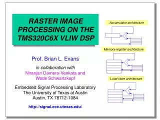
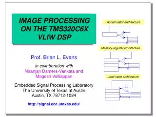
IMAGE PROCESSING ON THE TMS320C6X VLIW DSP. Accumulator architecture. Memory-register architecture. Prof. Brian L. Evans in collaboration with Niranjan Damera-Venkata and Magesh Valliappan Embedded Signal Processing Laboratory The University of Texas at Austin Austin, TX 78712-1084

E N D
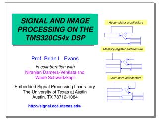
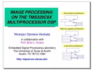
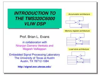
IMAGE PROCESSING ON THE TMS320C6X VLIW DSP Accumulator architecture Memory-register architecture Prof. Brian L. Evans in collaboration withNiranjan Damera-Venkata andMagesh Valliappan Embedded Signal Processing LaboratoryThe University of Texas at AustinAustin, TX 78712-1084 http://signal.ece.utexas.edu/ Load-store architecture
Outline • Introduction • 2-D FIR filters • Benchmarking a JPEG codec • Assembler, C compiler, and simulator • Code Composer Environment • Development boards • Conclusion
Introduction • Architecture • 8-way VLIW DSP processor • RISC instruction set • 2 16-bit multiplier units • Byte addressing • Modulo addressing • Applications • Wireless base stations • xDSL modems • Non-interlocked pipelines • Load-store architecture • 2 multiplications/cycle • 32-bit packed data type • No bit reversed addressing • Videoconferencing • Document processing
Introduction ArithmeticABSADDADDAADDKADD2MPYMPYHNEGSMPYSMPYHSADDSATSSUBSUBSUBASUBCSUB2ZERO LogicalANDCMPEQCMPGTCMPLTNOTORSHLSHRSSHLXOR DataManagementLDMVMVCMVKMVKHST ProgramControlBIDLENOP BitManagementCLREXTLMBDNORMSET C6x InstructionSet by Category (un)signed int/fixed multiplicationsaturation/packed arithmetic
Introduction .S Unit ADD NEGADDK NOTADD2 ORAND SETB SHLCLR SHREXT SSHLMV SUBMVC SUB2MVK XORMVKH ZERO .L Unit ABS NOTADD ORAND SADDCMPEQ SATCMPGT SSUBCMPLT SUBLMBD SUBCMV XORNEG ZERONORM .D Unit ADD STADDA SUBLD SUBAMV ZERONEG .M Unit MPY SMPYMPYH SMPYH Other NOP IDLE C6x Instruction Set by Category Six of the eight functional units can performadd, subtract, and register move operations
2-D FIR Filter • Difference equation y(n) = 2x(n1,n2) + 3x(n1-1,n2) + x(n1,n2-1) + x(n1-1,n2-1) • Flow graph a(m1,m2) x(n1,n2) m2 n2 m1 n1 (rows) • Vector dot product plus keep M1 rows in memory and circularly buffer input
2-D Filter Implementations • Store M1 x M2 filter coefficients in sequential memory (vector) of length M = M1M2 • For each output, form vector from N1 x N2 image • M1 separate dot products of length M2 as bytes • Form image vector by raster scanning image as bytes • Form image vector by raster scanning image as words Raster scan
2-D FIR Implementation #1 on C6x ; registers: A5=&a(0,0) B5=&x(n1,n2) B7=M A9=M2 B8=N2 fir2d1 MV .D1 A9,A2 ; inner product length|| SUB .D2 B8,B7,B10 ; offset to next row|| CMPLT.L1 B7,A9,A1 ; A1=no more rows to do|| ZERO .S1 A4 ; initialize accumulator|| SUB .S2 B7,A9,B7 ; number of taps leftfir1 LDBU .D1 *A5++,A6 ; load a(m1,m2), zero fill|| LDBU .D2 *B5++,B6 ; load x(n1-m1,n2-m2)|| MPYU .M1X A6,B6,A3 ; A3=a(m1,m2) x(n1-m1,n2-m2)|| ADD .L1 A3,A4,A4 ; y(n1,n2) += A3||[A2] SUB .S1 A2,1,A2 ; decrement loop counter||[A2] B .S2 fir1; if A2 != 0, then branch MV .D1 A9,A2 ; inner product length|| CMPLT.L1 B7,A9,A1 ; A1=no more rows to do|| ADD .L2 B5,B10,B5 ; advance to next image row||[!A1]B .S1 fir1 ; outer loop|| SUB .S2 B7,A9,B7 ; count number of taps left; A4=y(n1,n2)
2-D FIR Implementation #2 on C6x ; registers: A5=&a(0,0) B5=&x(n1,n2) A2=M B7=M2 B8=N2fir2d2 SUB .D2 B8,B7,B9 ; byte offset between rows || ZERO .L1 A4 ; initialize accumulator|| SUB .L2 B7,1,B7 ; B7 = numFilCols - 1|| ZERO .S2 B2 ; offset into image data fir2 LDBU .D1 *A5++,A6 ; load a(m1,m2), zero fill || LDBU .D2 *B6[B2],B6 ; load x(n1-m1,n2-m2) || MPYU .M1X A6,B6,A3 ; A3=a(m1,m2) x(n1-m1,n2-m2) || ADD .L1 A3,A4,A4 ; y(n1,n2) += A3 || CMPLT.L2 B2,B7,B1; need to go to next row?|| ADD .S2 B2,1,B2; incr offset into image [!B1] ADD .L2 B2,B9,B2 ; move offset to next row||[A2] SUB .S1 A2,1,A2 ; decrement loop counter ||[A2] B .S2 fir2; if A2 != 0, then branch ; A4=y(n1,n2)
2-D FIR Implementation #3 on C6x ; registers: A5=&a(0,0) B5=&x(n1,n2) A2=M B7=M2 B8=N2 fir2d3 ZERO .D1 A4 ; initialize accumulator #1|| SUB .D2 B8,B7,B9 ; index offset between rows || ZERO .L2 B2 ; offset into image data|| MVKH .S1 0xFF,A8 ; mask to get lowest 8 bits || SHR .S2 B7,1,B7 ; divide by 2: 16bit address ZERO .D2 B4 ; initialize accumulator #2|| ZERO .L1 A6 ; current coefficient value|| ZERO .L2 B6 ; current image value || SHR .S1 A2,1,A2 ; divide by 2: 16bit address|| SHR .S2 B9,1,B9 ; divide by 2: 16bit address Initialization
2-D FIR Implementation #3 on C6x (cont.) fir3 LDHU .D1 *A5++,A6 ; load a(m1,m2) a(m1+1,m2+1) || LDHU .D2 *B6[B2],B6 ; load two pixels of image x|| CMPLT.L2 B2,B7,B1; need to go to next row?|| ADD .S2 B2,1,B2; incr offset into image AND .L1 A6,A8,A6 ; extract a(m1,m2) || AND .L2 B6,A8,B6 ; extract x(n1-m1,n2-m2) || EXTU .S1 A6,0,8,A9 ; extract a(m1+1,m2+1)|| EXTU .S2 B6,0,8,B9 ; extract x(n1-m1+1,n2-m2+1) MPYHU .M1X A6,B6,A3 ; A3=a(m1,m2) x(n1-m1,n2-m2) || MPYHU .M2X A9,B9,B3 ; B3=a*x offset by 1 index|| ADD .L1 A3,A4,A4 ; y(n1,n2) += A3|| ADD .L2 B3,B4,B4 ; y(n1+1,n2+1) += B3 ||[!B1]ADD .D2 B2,B9,B2 ; move offset to next row||[A2] SUB .S1 A2,1,A2 ; decrement loop counter||[A2] B .S2 fir3; if A2 != 0, then branch; A4=y(n1,n2) and B4=y(n1+1,n2+1) Main Loop
JPEG • Encoder • Breaks image into 8 x 8 blocks • Computes DCT on each block • Quantizes DCT coefficients • Huffman encoding of coefficients • Decoder • Huffman decoding • Inverse DCT
Discrete Cosine Transform (DCT) • 1-D DCT of sequence x(n) defined on n in [0, N-1] • 2-D DCT is 1-D DCT applied in each dimension • Execution time for 1 8 x 8 block of 16-bit values • 230 cycles for inverse DCT and 226 cycle for DCT • www.ti.com/sc/docs/products/dsp/c6000/62bench.html
JPEG Codec Benchmarking on C6x • Used source code in The Data Compression Book • Not a full-featured JFIF reader/writer • Realizes JPEG core (DCT coefficients, Huffman codes) • Modifications to source code • Image is stored in 64 x 64 global array at 16 bits/pixel • Used 64 kbytes of on-chip RAM • Image data is loaded at startup into memory • Replaced file I/O routines with memory accesses • Implementation • Parallelizable loops (DCT) • Control dominated code (Huffman coding)
JPEG Codec Benchmarking on C6x 75-80% of execution time is spent on Huffman coding http://www.ece.utexas.edu/~bevans/hp-dsp-seminar/benchmarkJPEGC6x.pdf
Assembler, Compiler, and Simulator • Assembler optimizations • Assign functional units • Pack and parallelize linear assembly language code • Software pipelining • Compiler optimizations • Allocate registers • Software pipelining • Simulator
Code Composer Environment • Integrated software development on PC and Unix • C2x, C3x, C4x, C6x supported; C54x in October • Animated run with graphical signal display • Interactive profiling analysis and debugging • Open plug-in architecture • Full multiprocessing support under Windows • Uses TI C compiler and assembler • Probe point support for file I/O • Real-time data exchange (JTAG) 20 KB/s for C6x • Scripting language to add new GUI features • Free training available from San Jose office
Development Boards • Daytona Spectrum Signal C6x Board • 2 200-MHz TMS320C6201 VLIW DSPs (3200 MIPS) • 32 kB shared dual-port RAM for message passing • 512 kB of Synchronous Burst SRAM per processor • 16 MB of Synchronous DRAM per processor • Processor Expansion Module provides 400 MB/s • Hurricane PCI bridge • DSP~LINK3 I/O interface from processor Node A • http://www.spectrumsignal.com/
Spectrum Daytona C6x Board PEM Processor Expansion ModulePMC PCI Mezzanine Card http://www.spectrumsignal.com/catalog/Daytona.pdf
TI C6x Evaluation Module • 133-MHzC6201 • 256 kB 133-MHz BSRAM • 8 Mb100-MHzSDRAM • PCI bridge • JTAG • 16-bit audioDAC www.ti.com/sc/docs/tools/dsp/tmds3260a6201.html
Conclusion • Bottleneck for multimedia applications on C6x is bit stream parsing and variable-length decoding • Bit management routines are only available on S unit • 75-80% execution time for JPEG • 50% execution time for baseline MPEG-4 decoding • Integrated development environments • Texas Instruments Code Composer • Spectrum Signal extensions to Microsoft Visual C++ • C6x benchmarking for speech/audio applications • D. Talla, L. K. John, V. Lapinskii, and B. L. Evans, “Performance of Signal Processing and Multimedia Applications on SIMD, VLIW, and Superscalar Arch.,” 1999 IEEE/ACM Microarchitecture Sym., submitted.
Conclusion • Web resources • comp.dsp newsgroup: FAQ www.bdti.com/faq/dsp_faq.html • embedded processors and systems: www.eg3.com • on-line courses and DSP boards: www.techonline.com • TI C6x benchmarks:www.ti.com/sc/docs/products/dsp/c6000/62bench.htm • References • R. Bhargava, R. Radhakrishnan, B. L. Evans, and L. K. John, “Evaluating MMX Technology Using DSP and Multimedia Applications,” Proc. IEEE Sym. Microarchitecture, pp. 37-46, 1998.http://www.ece.utexas.edu/~ravib/mmxdsp/ • B. L. Evans, “EE379K-17 Real-Time DSP Laboratory,” UT Austin. http://www.ece.utexas.edu/~bevans/courses/realtime/ • B. L. Evans, “EE382C Embedded Software Systems,” UT Austin.http://www.ece.utexas.edu/~bevans/courses/ee382c/