Integrated Electric System for Bank's Office Building
80 likes | 188 Views
State-of-the-art electrical system with components like 11KV transformers, panel sections, ACB, VCB, and meters for efficient power management in a bank's office building at Patna.

Integrated Electric System for Bank's Office Building
E N D
Presentation Transcript
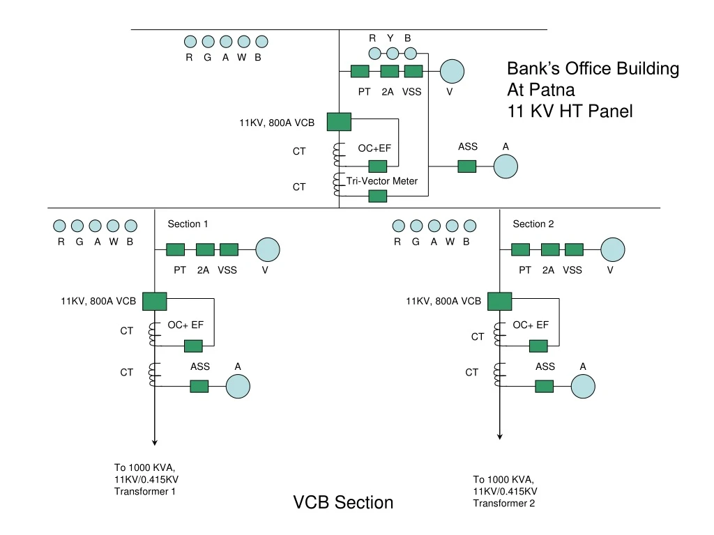
R Y B R G A W B Bank’s Office Building At Patna 11 KV HT Panel PT 2A VSS V 11KV, 800A VCB ASS A OC+EF CT Tri-Vector Meter CT Section 1 Section 2 R G A W B R G A W B PT 2A VSS V PT 2A VSS V 11KV, 800A VCB 11KV, 800A VCB OC+ EF OC+ EF CT CT ASS A ASS A CT CT To 1000 KVA, 11KV/0.415KV Transformer 1 To 1000 KVA, 11KV/0.415KV Transformer 2 VCB Section
From HT panel Section 1 From HT panel Section 2 11 KV 3x185 sq.mm. XLPE FRLS cables from HT panel 1000 KVA 11/0.415KV TR 1 1000 KVA 11/0.415KV TR 2 4x3.5x400 sq.mm. FRLS AL cable 0-500 V 0-500 V 2A VSS V 2A VSS V PM PM R Y B R Y B 2500A 4P MDO ACB Microprocessor 2500A 4P MDO ACB Microprocessor ASS A OC+EF ASS A OC+EF 0-1500 A 0-1500 A To APFC panel 1 To APFC panel 2 To LT panel Section 1 To LT panel Section 2 Main LT Panel - Incomer side Transformer Section
415 V LT panel 4x3.5x400 sq.mm. ALcable From LT breaker for Section 1 From LT breaker for Section 2 Main LT Panel 2500A 4P MDO ACB Bus Coupler 11 1 2 3 4 5 6 7 8 9 10 R Y B R Y B R Y B 1000A ACB 200A SDFU 100A SDFU 1000A ACB 630A SDFU 630A SDFU 400A SDFU 250A SDFU 200A SDFU 1000A ACB 400A SDFU To AMF Panel (EP-II) To AMF Panel (EP-III) To AMF Panel (EP-I) APFC-I Spare Spare ACB Panel No.2 APFC-II Spare Spare ACB Panel No.1 Main LT panel Outgoing side
From output of AMF panel of 600 KVA generator set 1000A 4P MDO ACB R Y B (With EF and OC protection) 0-500 V 2A VSS V ASS A 0-1500 A 1 2 3 4 5 6 7 200A SDFU 300A SDFU 200A SDFU 100A SDFU 100A SDFU 300A SDFU 630A SDFU AC Plant Lighting & fan CVPS New panel Spare Spare Spare Emergency Panel – EP-I
From output of AMF panel of 250 KVA generator set 400A SDFU R Y B 0-500 V 2A VSS V ASS A 0-400 A 1 2 3 4 5 63A SDFU 125A SDFU 200A SDFU 200A SDFU 125A SDFU Power load Computer load Executive area Spare Executive area Emergency Panel – EP-II
From output of AMF panel of 110 KVA generator set 250A SDFU R Y B 0-500 V 2A VSS V ASS A 0-300 A 1 2 3 4 200A SDFU 100A SDFU 63A SDFU 63A SDFU Existing 110 KVA load Spare Spare Spare Emergency Panel – EP-III
From LT panel From proposed generator set 630A SDFU R Y B 0-500 V 2A VSS V ASS A 0-400 A Digital PF meter A/M Switch 8x63A SDFU APF Relay 8 Nos. 63A TP contactors 8x25 KVAR capacitors APFC Panel