Download
1 / 29
580 likes | 1.22k Views
EE4220 Communications system. Wireless local loop (WLL). Dr. Hassan Yousif Electrical Engineering Department College of Engineering Salman Bin Abdulaziz University. Definition. What is WLL? - WLL is a system that connects subscribers to the local telephone station wirelessly.

E N D
EE4220 Communications system Wireless local loop (WLL) Dr. Hassan Yousif Electrical Engineering Department College of Engineering Salman Bin Abdulaziz University
Definition • What is WLL? - WLL is a system that connects subscribers to the local telephone station wirelessly. • Systems WLL is based on: • Cellular • Satellite (specific and adjunct) • Microcellular • Other names • Radio In The Loop (RITL) • Fixed-Radio Access (FRA).
WLL services • Desirable: • Wireless feature should be transparent • Wireline Custom features • Other: • Business related • Hunt groups, • Call transfers • Conference calling • Calling cards, coin phones • V.29 (9600bps) • ISDN (64kbps)
Advantages of WLL over Wired Approach • Cost – wireless systems are less expensive due to cost of cable installation that’s avoided • Installation time – WLL systems can be installed in a small fraction of the time required for a new wired system • Selective installation – radio units installed for subscribers who want service at a given time • With a wired system, cable is laid out in anticipation of serving every subscriber in a given area
Propagation Considerations for WLL • Most high-speed WLL schemes use millimeter wave frequencies (10 GHz to about 300 GHz) • There are wide unused frequency bands available above 25 GHz • At these high frequencies, wide channel bandwidths can be used, providing high data rates • Small size transceivers and adaptive antenna arrays can be used
Propagation Considerations for WLL • Millimeter wave systems have some undesirable propagation characteristics • Free space loss increases with the square of the frequency; losses are much higher in millimeter wave range • Above 10 GHz, attenuation effects due to rainfall and atmospheric or gaseous absorption are large • Multipath losses can be quite high
S D R Fresnel Zone • How much space around direct path between transmitter and receiver should be clear of obstacles? • Objects within a series of concentric circles around the line of sight between transceivers have constructive/destructive effects on communication • For point along the direct path, radius of first Fresnel zone: • S = distance from transmitter • D = distance from receiver
Atmospheric Absorption • Radio waves at frequencies above 10 GHz are subject to molecular absorption • Peak of water vapor absorption at 22 GHz • Peak of oxygen absorption near 60 GHz • Favorable windows for communication: • From 28 GHz to 42 GHz • From 75 GHz to 95 GHz
Effect of Rain • Attenuation due to rain • Presence of raindrops can severely degrade the reliability and performance of communication links • The effect of rain depends on drop shape, drop size, rain rate, and frequency • Estimated attenuation due to rain: • A = attenuation (dB/km) • R = rain rate (mm/hr) • a and b depend on drop sizes and frequency
Effects of Vegetation • Trees near subscriber sites can lead to multipath fading • Multipath effects from the tree canopy are diffraction and scattering • Measurements in orchards found considerable attenuation values when the foliage is within 60% of the first Fresnel zone • Multipath effects highly variable due to wind
WLL should provide… • Toll-quality service • Expand from a central office to about 5 miles • Low license cost • Subscriber costs equivalent or better than copper
Ideas for U.S. market • Supplement Copper Lines • Easier third telephone line • Data service • Fixed Mobile Users • Take phone wherever you want / charged on 2 levels • “home” could mean neighborhood • Charged regular mobile rate if you’re on the road
Cost Considerations • Wireless cost is constant over distance for WLL • Wireline depends on distance AND terrain
Connection Setup UWLL WANU WASU Transceiver Air Interface TWLL Trunk WLL Controller AM HLR PSTN Switch function • Wireless Access Network Unit(WANU) • Interface between underlying telephone network and wireless link • consists of • Base Station Transceivers (BTS) • Radio Controller(RPCU) • Access Manager(AM) • Home Location Register(HLR) Wireless Access Subscriber Unit(WASU) • located at the subscriber • translates wireless link into a traditional telephone connection
IEE802.16 Refernce Architecture SNI (STS Network Interface) BNI (BTS Network Interface) Air Interface Core Network Subscriber Network STS BTS Repeater (Optional) 802.16.1: 10GHz-66GHZ 802.16.2: Coexistence 802.16.3: 2-11 GHZ Subscriber Network = (LAN, PBX, IP-based network) Core Network = PSTN. Internet BTS = Base transceiver station STS = Subscriber transceiver station
Important Results of Fixed to Fixed Propagation in WLLs • Signal channel is not a Rayleigh fading channel: • Power control algorithms are simpler and can be utilized more effectively • Channel Randomness is lost: • Makes analysis difficult • Pathloss exponent is considerably smaller (Why?): • 20dB/dec compared to 40dB/dec • Decreases cell capacity • Allows for larger coverage area
Fixed to Fixed Propagation(cont’d) • No handoffs necessary: • Decreases hardware costs and system complexity • Increases quality of service through accurate traffic predictions • Allows usage of directional antennas: • Can greatly reduce interference and increase cell capacity 30dB 10dB -30dB -40dB 0o 60o 0o 120o 180o BS antenna Subscriber antenna
In-Cell Interference (CDMA) • I = (Nh – 1)aS NhaS a = voice activity factor Nh = total # of houses S = power received at cell site from every house
Out-of-Cell Interference • Pathloss: 20dB/dec as opposed to 40dB/dec need to take in account more tiers • Only from houses whose antennas are directed at the center cell base station
Interference from Another Cell • Blue area is region of interferers for C • It is Not a perfect pie shape • If w = (1/2)*(antenna width) (in radians) • W = w+2sin-1((R/D)sin(w/2)) • If w<<1 and R<<D: W = w (1+(R/D)) is the “pie” arc length
Per-Tier Interference • Integration over W and all the cells at tier n yields: In = [aNhSw/(3sqrt(3))][1/n] for n>4 • Interference is proportional to antenna width w and inversely proportional to the tier number. • Decreasing the antenna width can greatly reduce interference. • As the number of tiers approaches infinity, so does the total interference. Therefore, system capacity is a function of the total number of tiers in the system.
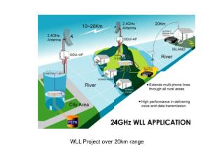
Examples of services provided • Marconi WipLL (wireless IP local loop) • Based on Frequency hopping CDMA • Internet Protocol 64kbps to 2.4Mbps rates Committed Information Rate or best effort service • Lucent WSS (wireless subscriber system) • 800 to 5000 subscribers per switch • Uses FDMA/FDD 12 Km to 40Km coverage • GoodWin WLL • DECT standards • 9.6 kbps rate • Specified conditions -5°С...+55°С, 20...75% humidity
Future of WLL / Overview • Depends on • economic development • existing infrastructure of a region • Offers • market competition • quick deployment • relatively reliable service at low costs
Free-Space Optics (FSO) • FSO uses lasers to transmit data, but instead of enclosing the data stream in a fiber optic cable, the data is transmitted through the air. • FSO systems can support data rates between 1.25G bit/sec to 150G bit/sec (theoretically) with link lengths that can vary from more than 600 feet up to about a mile. • Common FSO networks support around 2.5 Gbps of data, voice and video communications between 1000 to 2000 feet. • FSO transceivers can be located on a rooftop, on a corner of a building or indoors behind a window to support the last mile. • Highly secure line of sight communications in the last mile
Questions? Basie station