Transport Layer
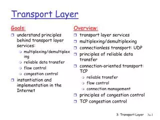
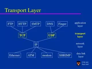
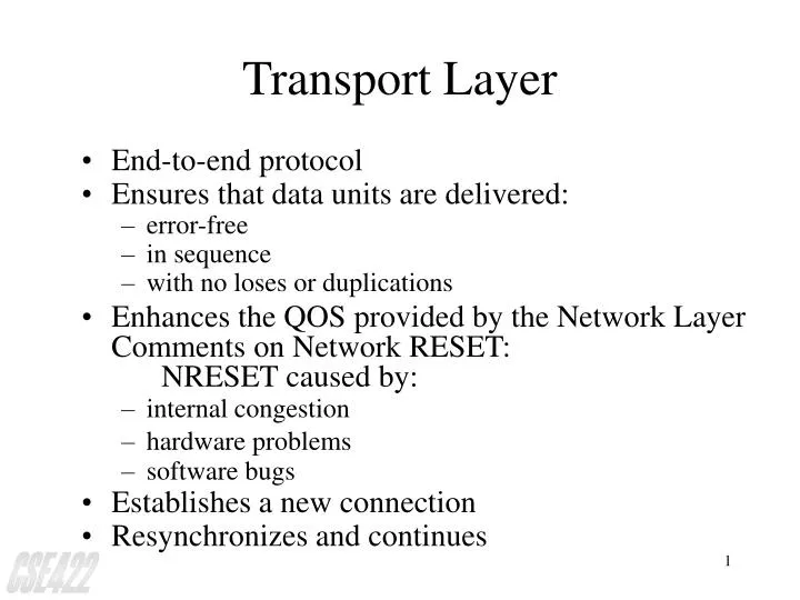
Transport Layer. End-to-end protocol Ensures that data units are delivered: error-free in sequence with no loses or duplications Enhances the QOS provided by the Network Layer Comments on Network RESET: NRESET caused by: internal congestion hardware problems software bugs

Transport Layer
E N D
Presentation Transcript
Transport Layer • End-to-end protocol • Ensures that data units are delivered: • error-free • in sequence • with no loses or duplications • Enhances the QOS provided by the Network Layer Comments on Network RESET: NRESET caused by: • internal congestion • hardware problems • software bugs • Establishes a new connection • Resynchronizes and continues
Transport Layer (cont.) A B 5 4 3 1-2 Application (or Session) Layer Application (or Session) Layer TSAP Interface Services provided to the session layer TPDU Transport Entity Transport Entity Transport protocol Network layer services used by transport layer NSAP Network Layer Network Layer
Transport Layer (cont.) QOS parameters are specified by the Transport users when a connection is requested. Transport Service Primitives: • Provided for both: • Connection-oriented service • Connectionless service
Transport Layer Quality of Service Parameters Connection establishment delay Connection establishment failure probability Throughput Transit delay Residual error ratio Transfer failure probability Connection release delay Connection release failure probability Protection Priority Resilience
Transport Layer (cont.) IMP Physical Communication channel (a) Environment of the data link layer IMP Host Subnet (b) Environment of the transport layer
Types of serviceoffered by the network layer Network type Description A Flawless, error-free service with no N-RESETS B Perfect packet delivery, but with N-RESETS C Unreliable service with lost and duplicated packets and possibly N-RESETS
TSAP, NSAP, andConnections (cont.) 3. Process server creates time-of-day server & tells it where to listen 1. Process server listens on well-known TSAP 4. Time-of-day server 5. Process server tells user where to listen and closes this connection. 6. User connects to the time-of-day server 2. User connects to Well-known TSAP How a user process in Host A establishes a connection with a time-of-day server
Seven States in Transport Entity Each connection maintained by the transport entity is always in one of seven states, as follows: 1. Idle - Connection not established yet. 2. Passive Establishment Pending - CONNECT has been executed and CALL REQUEST sent. 3. Active Establishment Pending - A CALL REQUEST has arrived; LISTEN has not been done. 4. Established - The connection has been established. 5. Passive Disconnect Pending - The user is waiting for permission to transmit a packet. 6. Active Disconnect Pending - A RECEIVE has been done. 7. Idle - A DISCONNECT has been done locally.
Connection Management Scheme Connection request TPDU received Connect primitive executed Idle Passive Establishment Pending Active Establishment Pending Established Connection request TPDU received Connect primitive executed Passive Disconnect Pending Active Disconnect Pending Disconnection request TPDU received Disconnect primitive executed Idle Disconnect primitive executed Disconnection request TPDU received Transition labeled in italics are caused by packet arrivals The solid lines show the client’s state sequence. The dashed lines show the server’s state sequence.
Networking in UNIX(Berkeley Sockets) Berkeley Primitives implemented as a set of system CALLs, and allow application programs to access communication protocols via SOCKET concept. Note: Socket == OSI TSAP
The Principal Transport Service Calls in Berkeley UNIX Socket Create a TSAP of a given type Bind Associate an ASCII name to a previously created socket Listen Create a queue to store incoming connection requests Accept Remove a connection request from the queue or wait for one Connect Initiate a connection with a remote socket Shutdown Shutdown Send Send a message through a given socket Recv Receive a message on a given socket Select Check a set of sockets to see if any can be read or written
Implementation of an API • Sockets (Sockets Interface by Berkeley) • System V UNIX (Sockets Interface by AT&T) • WINSOCK (Windows Sockets Interface by Microsoft)
Implementation of an API (cont.) Application1 Application2 Applicationn Application Programs ....... DLL containing socket interface procedures Socket API TCP/IP functions DLL containing TCP/IP software Operating System Functions I/O functions The organization of the socket API and TCP/IP code in a Dynamic Linked Library under Windows 95. One copy of a DLL is loaded into memory when needed; all applications share the copy
Implementation of an API (cont.) Application1 Application2 Applicationn Application Programs ....... DLL containing socket interface procedures Socket API TCP/IP functions & I/O functions Operating Systems The organization of the socket API and TCP/IP code under Windows NT. Although code for TCP/IP is part of the operating system, procedures for the socket API are part of a DLL
Internet Transport Protocols • TCP (connection-oriented): Designated to provide a reliable end-to-end byte stream over an unreliable internetwork. • UDP (connectionless) - Just IP with a short header added. • TCP - Designed to dynamically adapt to properties of the internetwork and to be robust in the face of many kind of failures.
Internet Transport Protocols (cont.) • Each machine supporting TCP has a TCP transport entity (e.g., user process or part of the kernel that manages TCP streams and interfaces to the IP layer). • A TCP entity accepts user data streams from local processes, breaks them up into pieces not exceeding 64K bytes and sends each piece as a separate IP datagram. • When IP datagrams containing TCP data arrive at a machine, they are given to the TCP entity, which reconstructs the original byte streams
The TCP Service Model • TCP service is obtained by having both the sender and receiver create end pts, called sockets. • Each socket has a socket number (address), consisting of the IP address of the host and a 16-bit number local to that host, called a port (TCP name for a TSAP) • To obtain TCP service, a connection must be explicitly established between a socket on the sending machine and the receiving machine.
The TCP Service Model (cont.) • All TCP connections are full duplex and point-to-point • TCP does not support multicasting or broadcasting • Push Flag - tells TCP not to delay the transmission • Urgent Data - (e.g., Interactive user hits the DEL or CTRL-C key) The sending application puts some CTL information in the data stream and gives it to TCP, along with the urgent flag.
The TCP Protocol (overview) • The sending and receiving TCP entities exchange data in the form of segments • Basic protocol - sliding window; when the sender transmits a segment, it also starts a timer, When the segment arrives at the destination, the receiving TCP entity sends back a segment (with data if any exists, otherwise without data) bearing an ACK.
The TCP TPDU Structure Source Port Destination Port Sequence Number Piggyback Acknowledgement TCP Header TCP Header Length U R G E O M A C K R S T S Y N F I N Window Checksum Urgent Pointer Options (0 or more 32 bit words) Data
TCP Congestion Control • Congestion – Severe delay caused by an overload of datagrams at one or more router. • Internet TCP algorithms assume that timeouts are caused by congestion. • To avoid congestion, the TCP standard now recommends using two techniques • Slow – start • Multiplicative decrease • Note: TCP must remember the size of the receiver’s window. A second limit, congestion window, must be maintained. • Allowed_window = • min (receiver_advertisement,congestion_window)
Transmission rate adjustment Transmission network Internal congestion Small-capacity receiver Large-capacity receiver (b) (a) • A fast network feeding a low-capacity receiver. • A slow network feeding a high-capacity receiver.
Timeout 1/2 Threshold Slow Start 44 40 36 32 28 Congestion window (kilobytes) 24 20 16 12 8 4 0 0 2 4 6 8 10 12 14 16 18 20 22 24 Transmission number An example of the Internet congestion algorithm
Estimation of Congestion Window Size • TCP assumes that most datagram loss comes from congestion and uses the following strategy: • MULTIPLICATIVE DECREASE CONGESTION AVOIDANCE • Upon loss of segment, reduce the congestion window by half (down to a minimum of at least one segment). For those segments that remain in the allowed window, backoff the retransmission timer exponentially. • (comment) If congestion is likely, TCP reduces the volume of traffic exponentially and the rate of retransmission exponentially.
TCP Recovery When Congestion Ends • SLOW-START (ADDITIVE) RECOVERY: • Whenever starting traffic on a new connection or increasing traffic after a period of congestion, start the congestion window at the size of a single segment and increase the congestion window by one segment each time an Ack arrives. • (comment) Slow start avoids swamping the internet with additional traffic immediately after congestion clears or when new connections suddenly start.
Congestion Avoidance Phase • To avoid increasing the window size too quickly, TCP adds one additional restriction: • Once the congestion window reaches one half of its original size before congestion, TCP enters a congestion avoidance phase and slow down the rate of increment. • During congestion avoidance, it increases congestion window by 1 only if all segments and the window have been acknowledged.
The TCP/IP Protocol Suite Hierarchy Versus Layering: TCP/IP--the task of communications is broken up into modules or entities that may communicate with peer entities in another system. One entity within a system provides services to other entities and, in turn uses the services of other entities. Good software design practice dictates that these entities be arranged hierarchically.
TCP/IP Architecture Based on the view of a communication that involves three agents: • Process • Hosts • Networks Note: Processes (fundamental entities that communicate), execute on hosts, which often support multiple simultaneous processes. Communication between processes take place across the networks to which the hosts are attached.
TCP/IP Architecture (cont.) Protocols are Organized into 4 Layers: • Network access layer • Internet layer: IP (MIL-STD-1977) • Host-host layer: TCP (MIL-STD-1978) • Process/application layer: FTP (MIL-STD-1980); SMTP (MIL-STD-1981); TELNET (MIL-STD-1982)
TCP/IP Architecture (cont.) Network access layer: Contains those protocols that provide access to a communication network. Protocols at this layer are between a communication node and an attached host. A function of all these protocols is to route data between host attached to the same network. Other services may include: flow control, error control and various QoS features.
TCP/IP Architecture (cont.) Internet layer: Consists of procedures required to allow data to traverse multiple networks between hosts. Thus, it provides a routing function, and usually implemented within hosts and gateways.
TCP/IP Architecture (cont.) Host-to-host layer: Contains protocol entities with the ability to deliver data between two processes on different host computers. A protocol entity at this level may or may not provide a logical connection between higher-level entities. Other possible services include error and flow control and the ability to deal with control signals not associated with a logical data connection.
TCP/IP Architecture (cont.) Process/Application Layer: Contains protocols for resource sharing (e.g., computer-to-computer) and remote access (e.g., terminal-to-computer).
Application-level Internet Services • E-mail • File Transfer • Remote Login
TCP/IP Internet Domain Names • The mechanism that implements a machine name hierarchy for TCP/IP internets is called the Domain Name System. This system uses a hierarchical naming system known as domain names. • Hierarchical machines are assigned according to the structure of the organizations obtained authority for parts of the namespace, not necessarily according to the structure of the physical network interconnections.
Mapping Domain Names to Addresses • The Domain mechanism for mapping names to addresses consists of independent, cooperative system called name server. A name server is a server program that supplies name-to-address translation to IP addresses. • Often, name server software executes on a dedicated processor, and the machine itself is called the name server.
Domain Address Resolution • When a domain server receives a query, it checks to see if the name lies in the sub-domain for which it is an authority. If so, it translates the name to an address according to its database, and appends an answer to the query before sending it back to the client. • If the name server cannot resolve the name completely, it contacts a domain server that can resolve the name & returns the answer to the client.
The Top-Level Internet Domains and Their Meanings Domain Name Meaning COM EDU GOV MIL NET ORG ARPA INT country code Commercial organizations Educational Institutions Government Institutions Military groups Major network support centers Organizations other than those above Temporary ARPANET domain (obsolete) International organizations Each country (geographic scheme) Although labels are shown in upper case, domain name system comparisons are insensitive to case, EDU is equivalent to edu
Domain Name Servers in a Tree Root Server server for .com server for .edu server for .gov server for .us ....... server for dec.com server for msu.edu server for nsf.gov server for va.us The conceptual arrangement of domain name servers in a tree that corresponds to the naming hierarchy. In theory, each server knows the addresses of all lower-level servers for all sub-domains within the domain it handles
Hierarchical organizationof the DNS unnamed root .... .... Top Level Domains arpa com edu gov mil net ae us zw United Arab Emirates Zimbabwe 2nd Level Domains in-addr msu va 140 cps reston cps.msu.edu 252 cnri cnri.reston.va.us 13 generic domains country domains 33 33.13.252.140.in-addr.arpa
Caching: The key to Efficiency • The cost of looking up nonlocal names can be extremely high if resolvers send each query to the root server. So, Internet name server can use name caching to optimize the costs. • Each server maintains a cache of recently used names as well as record of where the mapping information for that name was obtained. Note: cache entries are timed stamped, and deleted after a specified time period. • When a client asks the server to resolve a name, the server first check to see if it has authority to resolve it by the standard procedure. If not, the server checks the cache to see if the name has been resolved recently.
Internet Electronic Mail, with a relay system at both ends. Sending Host user at a terminal one organi- zation user agent queue of mail to be sent local MTA local MTA local MTA queue of mail relay MTA across the Internet
Internet Electronic Mail, with a relay system at both ends (cont.) across the Internet queue of mail relay MTA one organi- zation local MTA local MTA local MTA user agent user mailboxes user at a terminal Receiving Host
Simple Mail Transfer Protocol (SMPT) NOTE: Five SMPT commands are used to send the mail: HELO, MAIL, RCPT, DATA and QUIT S: 220 Beta.GOV Simple Mail Transfer Service Ready C: HELO Alpha.EDU S: 250 Beta.GOV C: MAIL FROM:<Smith@Alpha.EDU> S: 250 OK C: RCPT TO:<Jones@Beta.GOV> S: 250 OK C: RCPT TO: <Green@Beta.GOV> S: 550 No such user here C: RCPT TO:<Brown@Beta.GOV> S: 250 OK C: DATA S: 354 Start mail input; end with <CR><LF>.<CR><LF> C: ... sends body of mail message ... C: ... continues for as many lines as message contains C: <CR><LF>.<CR><LF> S: 250 OK C: QUIT S: 221 Beta.GOV Service closing transmission channel
HTTP FTP TELNET NFS DNS SNMP RPC transport layer TCP UDP network layer IP data link layer Layering of TCP/IP-based protocols
Network-level Internet Services • Connectionless packet delivery service • Reliable stream transport service • Network technology independence • Universal Interconnection • End-to-end ACKs • Application Protocols Standards