Lecture 11: Internetworking
470 likes | 486 Views
1007ICT Introduction to Computer Systems & Networks. Lecture 11: Internetworking. Dr. Ruben Gonzalez. Application. Presentation. Session. Transport. Network. Data Link. Physical. The Network Layer. Internetwork (IP) Protocol Addressing Routing Connecting LANs Backbone networks

Lecture 11: Internetworking
E N D
Presentation Transcript
1007ICT Introduction to Computer Systems & Networks Lecture 11: Internetworking Dr. Ruben Gonzalez
Application Presentation Session Transport Network Data Link Physical The Network Layer • Internetwork (IP) Protocol • Addressing • Routing • Connecting LANs • Backbone networks • Virtual LANs Called the IP Layer in the TCP/IP model
Why Interconnect Networks? • Often you need to connect one local area network to another network. • To separate / connect one corporate division with another. • To connect two LANs with different protocols. • To connect a LAN to the Internet. • To break a LAN into segments to relieve traffic congestion. • To provide a security wall between different users.
Connecting Networks • In large networks we need some means to allow one-on-one communication between any two nodes. • If the the communicating nodes are connected to a single medium (eg in a LAN) we can use: • Direct point-to-point connection • Connection to a common bus in a multipoint configuration • If we are connecting different networks together then some type of switching needs to be used to exchange data from devices in the source network to the appropriate destination network.
Connecting Networks • This requires a network device to bridge the two networks so that packets can be routed from one network to the other. • May need to translate different network protocols • Needs to route packets between networks • Example Network devices: Bridge / Router / Gateway • It also requires a network-wide protocol that can: • Handle addressing across the entire network • Determine how to route packets to their destinations • Perform end-to-end error handling (inthe transport layer)
TCP/IP Network Layer (IP) • IP (Internetwork Protocol) is an unreliable, connectionless protocol. • The packets in IP are called datagramsand have the following format:
Network Addressing • In order for messages to get to the correct destination, addresses must be specified. • Three main levels of addressing are used in a TCP/IP network:
IP Addresses • In TCP/IP the network layer address is called the IP address • Five classes of addresses are defined to cater for the needs of various organisations • The format of IP addresses is as follows:
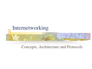
129.8.0.1 129.8.9.14 Class B 220.3.6.7 129.8.0.0 134.18.0.0 Class B 129.8.7.15 134.18.1.29 134.18.0.209 222.13.16.7 222.13.16.12 220.3.6.5 G G 220.3.6.0 222.13.16.0 134.18.0.2 Class C 134.18.0.210 220.3.6.9 a.b.c.d To Internet R 220.3.6.1 134.18.5.9 207.42.56.10 207.42.56.0 207.42.56.11 R Class A 124.0.132.119 124.0.0.0 124.1.0.5 124.1.1.15 124.1.1.12 124.0.12.2 TCP/IP Internet Addressing Example Note that devices with more than one network connection have more than one network (IP) address.
Sub-networks • Subnets are a method of splitting an allocated IP network address into smaller portions that are identified by a subnet number. • The subnet mask is used to determine the sub-network portion of an IP address; i.e. where the subnet number ends and the host number begins • A mask is a 32-bit word that has a 1 for all bits that indicate the subnet, and 0 for all bits designating the host, and is ANDed with the IP address to extract the subnet number. • Examples, • The subnetwork mask for an organisation that has been assigned a class C network address and wishes to use the first three bit of the last byte to designate the subnet would be: 255.255.255.224
Subnet Addressing Outside world Class B Address: 128.11.x.x Netid Hosttid 128.11.3.31 Subnet Mask: 255.255.255.x Hosttid Netid Netid Subnetid Within Organisation
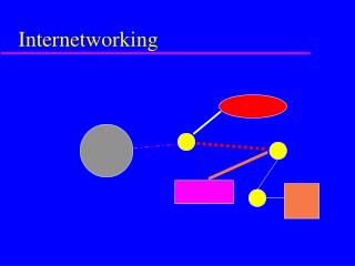
141.14.2.1 141.14.2.10 141.14.2.9 141.14.2.0 141.14.4.1 141.14.4.11 subnet subnet R 141.14.4.0 141.14.12.10 141.14.12.11 141.14.4.43 141.14.4.96 141.14.12.0 141.14.12.109 subnet 141.14.12.12 Sub-networking Example Class B Address: 141.14.0.0 Subnet Mask: 255.255.255.0
Other TPC/IP Network Layer Protocols • Address Resolution Protocol (ARP) • Associates an IP (network) address with the physical address (the ethernet address on the NIC). • Internet Control Message Protocol (ICMP) • Used by hosts and routers to inform sender of problems with datagram delivery. • Internet Group Message Protocol (IGMP) • Used to support multicasting. • Used by a router to determine which hosts on a LAN belong to the multicast group defined by a given class D address.
Address Resolution Protocol -ARP I’m looking for the physical address of the node whose IP address is 141.14.22.1 Broadcast ARP Request I’m the node you’re after and my physical address is C0-12-AF-BG-33-01 Unicast ARP Response
Switching • In many networks rather than directly connecting computers together they are connected to a devices called network switches or multipoint routers • Communication between any two nodes can involve passing through several switches • Two main types of switching • Circuit switching • Packet switching
Circuit Switching • Permits any two network devices can talk together at any one time – like telephones • Creates a dedicated physical point-to-point connection to exist between the devices for the duration of the communication • Data travels in a continuous stream of bits • Advantages: • Secure, most suitable for continuous (streaming or real-time) data • Disadvantages • Inefficient for typical (non audio-video) data
Packet Switching • Any device can simultaneously connect to any number of other devices in the network • Data is broken up into packetsbefore transmission • No dedicated physical connection is created during the transmission • Each packet can take a different path to reach its destination • Each link is shared by packets from all other devices • Advantage: • More efficient for typical computer data communications • Disadvantage: • Harder to secure, less suitable for continuous data
Routing • Routing is the process of determining the route or path through the network that a message will travel in order to get from the sender to the receiver. • The paths selected for end-to-end data transfer are taken by switching packets onto correct links at each network node. • Every computer or node that performs routing has a routing table developed by the network manager that specifies how message will travel through the network.
Routing • The goal is to select the most efficient path through the nodes, which may depend on: • Performance – delay, # hops, node throughput, link capacity • Status and traffic load of individual switches & links. • Desirable properties for routing algorithms are: • correctness, • robustness (cope with topology and traffic changes), • fairness (give all messages equal opportunity) • simplicity, stability (always work towards equilibrium), • Minimise delay & maximise throughput. • There are various approaches to routing: • Static (fixed) -which always uses the same paths • Random - just sends the packet on any one path • Broadcast - sends the packet on all possible paths • Dynamic (adaptive) adjusts to changes in the network
Routing Methods -1 • Fixed or Static Routing • Uses a routing table kept at each node that is updated by the network manager when there has been a change of network topology by adding or removing computers. • Incoming packets are switched onto outgoing links chosen by looking up the destination in the routing table. • Always uses the same paths regardless of network traffic or link availability. If a link in a particular path is down then communication to that destination is impossible. • Random Routing • The simplest method, a node randomly selects only one outgoing path for sending a packet. The selection may be made on a round-robin fashion. • It may take a while for a packet to reach its destination and the method generates higher than necessary traffic
Routing Methods -2 • Flooding or broadcast routing • Packets are retransmitted to all links except the one on which it arrives. Multiple copies of the packet may arrive at the destination. • Since all possible paths are attempted it has a higher chance of success. But it creates a very high network traffic load. • Adaptive or Dynamic Routing • An initial routing table is created by the network manager, but is continuously updated by the computers themselves to select the “best” path at any instance under changing network conditions. • Hence all packets addressed to a particular destination may travel a different path even if they belong to a single message • Uses adaptive algorithms to calculate updates to routing tables • To stop packets going endlessly around in a loop: • One can remember the identity of the packet it has sent and discard any duplicates that arrive at the same node • A hop count field can be included with each packet that is decremented by each router before forwarding it, if the hop count becomes zero the packet is instead destroyed.
Distributed Routing • Each node in the network calculates its own routing table using a formal routing protocol by either: • All nodes periodically transmitting their status to all other nodes in the network for these to update their routing tables. Typical status is Link delay – queue length on output ports • Use of adaptive algorithms where each node automatically builds & updates its own routing table according to changing topology. • Example adaptive algorithm : • Frame forwarding – when a packet arrives, and its destination is in the routing table the packet is sent on the right link. Otherwise all links are flooded with the packet except the link on which it arrived. • Address learning – when a packet arrives its source is looked up in the routing table. If it is not found then add it to the table. • Loop Resolution – when a packet arrives the node evaluates if the packet is going round in circles if it is then it will be discarded • There are 3 commonly used dynamic routing protocols • Routing Information Protocol (RIP). • Internet Control Message Protocol (ICMP). • Open Shortest Path First (OSPF).
Connecting LANs • To connect a local area network to another LAN or to a wide area network you must consider: • Frame format • Each LAN protocol has its own frame format, hence conversion is necessary. • Payload size • The maximum allowable length for the data field varies between protocols. This may require a frame to be subdivided before being forwarded. (Eg from token ring to Ethernet). • Data rate • Different protocols operate at different data rates (as well as different LANs running the same protocol – eg 10Base-T and 100Base-T). Frames travelling from a faster to a slower LAN must be buffered accordingly. • Address bit order • the binary representation of physical addresses varies between protocols. Appropriate conversion must be performed.
Devices for Connecting LANs • Different devices are need to connect different types of networks. • Ethernet switches, can be used to interconnect segments of a LAN. • LAN-to-LAN connections are often performed with a bridge-like device. • LAN-to-WAN connections are usually performed with a router. • Repeaters are used to extend the length/range of a physical medium
Repeaters and Hubs • Operate purely at the physical layer. • Propagate all traffic in both directions (Transparent) • Used to extend the length of a LAN segment beyond the normal limit imposed by the medium. • Regenerate all signals received on one segment and forwarding (repeats) them onto the next. • They use the same data link & network protocols • When a workstation transmits to a hub, the hub immediately forwards the data packet out all connecting links.
Switches • Switches operate at the data link layer • Switches connect different segments of a single LAN together or interconnect two or more workstations. • Workstations that connect to a switch each use dedicated point-to-point segments. This is a very efficient way to isolate heavy users from the network. • Like a bridge, switches observe traffic flow and perform routing. • When a packet arrives at a switch, the switch examines the destination address and forwards the frame out the one necessary connection. • Switches are fast enough to support multiple simultaneous data transfers
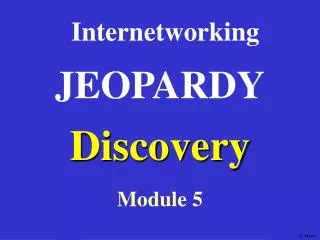
Maximum total capacity = N x 10 Mbps Switch 10 Mbps 10 Mbps Switches vs Hubs Maximum total capacity = 10 Mbps Hub 10 Mbps 10 Mbps 10 Mbps 10 Mbps
Bridges • A bridge (or bridge-like device) can be used to connect two similar LANs, such as ethernet LANs. • A bridge can also be used to connect two closely similar but different LANs, such as a CSMA/CD LAN and a CSMA/CA 802.11 Wireless LAN. • Bridges buffers all frames in their entirety before forwarding them, introducing an additional store-and-forward delay. • Bridges don’t perform flow control and may overload during periods of high traffic due to needing to translate protocols. • The bridge examines the destination address in a frame and either forwards this frame onto the next LAN or does not. • The bridge examines the source address in a frame and places this address in a routing table, to be used for future routing decisions. • Like switches, bridges operate at the data link layer
Bridges 802.11 Wireless LAN 802.2 Ethernet LAN Bridge
Routers • Routers operate at the network layer • Connect two or more LANs with same network layers but different Data Link or physical Layers. • Can determine which is the best path for a message to take between networks. • A router can be a special purpose “black box”, a computer with several NICs or a special network software module within a computer. • It is quite common now for bridges to be bridge-routers and the distinction between the two is becoming blurred.
Routers in a Network 802.3 Ethernet LAN ISDN / ADSLNetwork Router
Terminology… • The terminology used in the marketplace may differ substantially and tends to change as fast a catalogues can be printed! For example, one vendor’s bridge may provide the functions of another’s router. • Some other networking devices that are available: • Multiprotocol bridges – translate between different data link layer protocols. • Multiprotocol routers – can understand several different network layer protocols. • Protocol filtering bridges – multiprotocol bridges that forward only packets of a certain type. • Encapsulating bridges – connect networks with different data link protocols. • Layer-3 switches (IP switches) –switch messages base on network layer address.
Application Presentation Session Transport Network Data Link Physical The Transport Layer • Network Wide Error Control • Datagrams and Virtual Circuits • Transport Control Protocol (TCP) • User Datagram Protocol (UDP) Internet Protocol Tree Application Transport Network
Network Wide Error Control • The data link layer only checks errors that occur within a single physical network. • The transport layer also needs to perform error control to handle any errors that occur between networks.
Sequence Control • Messages are segmented into individual packets at the source and reassembled at the destination. • Care needs to be taken that the packets are reassembled in the correct order. • Sequence numbers added to each packet makes this easy to do. II IV VIII I VI IX III
V/V Packet Loss Control • Sequence numbers also tell the receiver if all the packets have been received. • If any packets are lost along the way, the receiver needs to request that they be retransmitted. II/V III/V I/V
V III Duplication control • Sometimes the receiver gives up waiting for a packet too soon and requests that it be retransmitted just before it arrives. • This may result in duplicate packets being produced and received. • Obviously, the duplicates must be discarded. • Once again, sequence numbers come to the rescue! V/V IV/V II/V III/V I/V
Flow Control • Flow control similar to that used by the data link layer, however, the flow control is from end-to-end.
Types of Packet Switching • Data can be delivered across a packet switched network in two different ways: • Connectionless – Datagram • Each packet travels independently through the network, • Uses no error control, so incorrect frames are just discarded • Called an unreliable or best try service • Example: UDP – User Datagram Protocol • Connection-oriented - Virtual circuit • A logical connection is established between the source and destination before any packets are sent that defines a path. • Packets from a single message travel along the same path. • This logical connection is called a virtual circuit. • Once a single pathway exists for acknowledgements be made error checking and flow control can be used . • Example: TCP - Transmission control protocol
3 4 2 1 3 4 1 3 2 4 4 2 1 4 3 2 1 2 1 2 1 2 1 2 1 Connectionless vs Connection-Oriented Services • Connectionless • Datagrams • Connection-oriented • Virtual Circuit
User Datagram Protocol (UDP) • UDP provides a connectionless service with limited error control. No sequence numbers means that lost or duplicated packets can’t be detected. • Used for real-time data such as streaming video and audio. Header Format: Source port address Destination port address Length Header checksum 2 bytes Datagram Format: Header Data 8 bytes variable
Transmission Control Protocol (TCP) • Connection oriented transport protocol that provides all the functionality defined for the transport layer in the OSI model. • Packets are called segments:
Switched Virtual Circuit 1. Connection Establishment 2. Data Transmission 3. Connection Termination
Connection setup & termination Three-Way Handshake
Sample Exam Questions • What are some reasons for interconnecting networks? • What is the function of the network layer protocol in an internetwork? • Compare and contrast the use and operation of a (layer-2) switch and a router. • What are the two main types of switching? List the relative advantages and disadvantages of each. • Why do we need end-to-end error and flow control in the transport layer?