Download

1 / 36
460 likes | 841 Views
Stirling Engines & Electric Motors. A Stirling Engine which runs of a coffee cup http://jlnlabs.imars.com/html/stirling.htm.

E N D
A Stirling Engine which runs of a coffee cuphttp://jlnlabs.imars.com/html/stirling.htm • created on January 31, 2001 - JLN Labs - Last update February 2, 2001, All informations and diagrams are published freely (freeware) and are intended for a private use and a non commercial use.
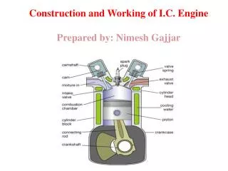
Stirling-cycle engines • They has been patented in 1816 by Robert Stirling, a Scottish engineer. • The Stirling-cycle engine runs on the expansion and contraction of a gas forced between separate hot and cold chambers. • The resulting change in volume is then used to drive a piston, which can then be used to power external devices. • Imagine a compact, quiet power plant that delivers some kilowatts of electricity-plus hot water for heating. Let's say this power source is also virtually pollution-free, able to burn most fuels, and requires minimal maintenance. • I have purchased my own Stirling Engine model at the American Stirling Company, the model is the "Coffee Cup Stirling Engine MM-1". • This model works very well and turn at a high speed on a simple coffee cup filled with water and heated in a simple microwaves oven...
When the air inside the engine is heated it expands and pushes up on the piston. • Then when the air is cooled, it contracts and pulls down on the piston.
See the video of the Stirling engine MM-1 inaction • Video Amination: Using RealPlayer F:\能源運用與環境\發電機\stirling.rm
How a Stirling Engine Works-http://www.infiniacorp.com/technology/how_stirling_works.htm, • Originally developed by Robert Stirling in 1816, the Stirling cycle uses a working fluid (typically Helium, Nitrogen or Hydrogen gas) in a closed cylinder containing a piston. • Heated on one end and cooled on the other, the expansion and cooling of the gas drives the piston back and forth in the cylinder. • Amination:piston_engine[1].swf (Courtesy of NASA) Animation of a 55 We Stirling TDC
How a Stirling Engine Works-http://www.infiniacorp.com/technology/how_stirling_works.htm, • The work performed by this piston-motion is used to drive a generator (in Infinia’s case, a patented linear alternator) or to create pressure waves to drive a compression process. • The cycle can be operated in reverse by using the generator as a motor to drive the piston. • In this case, the continuous expansion and cooling of the working fluid caused by the piston motion creates a cooling effect. • These types of systems are called Stirling coolers (also referred to as cryocoolers) and can maintain temperatures as low as 10 Kelvin (-263°C, and –442 °F) • The partners at the NASA Glenn Research Center, have put together some excellent educational materials about the science of the Stirling Cycle. Learn More.
Various Stirling cycle configurations in operation-http://www.grc.nasa.gov/WWW/tmsb/stirling/doc/stirling_animation.html • The following animations illustrate various Stirling cycle configurations in operation. Click on the image to view the animation. They take a while to load. • The 55 We Stirling TDC operating in a vertical orientation created by Jeff Schreiber. • Amination:piston_engine[1].swf • (Courtesy of NASA)
Dual opposed 55 We Stirling TDCs-Created by Jeff Schreiber • Stirling Animation - Dual Opposed obtained from NASA Glenn Research Center Thermo-Mechanical Systems Branch • http://www.grc.nasa.gov/WWW/tmsb/stirling/animation/anim_2.html
Stirling Rhombic drive http://www.grc.nasa.gov/WWW/tmsb/stirling/animation/anim_3.html Created by Salvatore Oriti, 5490 co-op student
Stirling Rhombic drive http://www.grc.nasa.gov/WWW/tmsb/stirling/animation/anim_4.html Created by Jeff Schreiber
Stirling Animation - Beta Configuration-Created by Salvatore Oriti, 5490 co-op student • Amination file: animation_dual_opposed_with_rods_jeff.gif • Last Revision: March 20, 2002
Stirling Animation – Gamma (L) & Beta (R) Configurations-Created by Kyle Schneider, 5490 summer student
HyperPhysics-Educational Web site http://hyperphysics.phy-astr.gsu.edu/hbase/electric/dccircon.html#c1
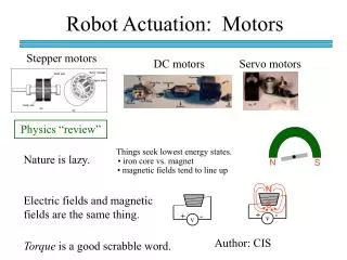
How Does an Electric Motor Work? http://hyperphysics.phy-astr.gsu.edu/hbase/magnetic/mothow.html#c1
DC Motor Operation • This is an active graphic. Click on bold type for further illustration.
Commutator and Brushes on DC Motor • To keep the torque on a DC motor from reversing every time the coil moves through the plane perpendicular to the magnetic field, a split-ring device called a commutator is used to reverse the current at that point. • The electrical contacts to the rotating ring are called "brushes" since copper brush contacts were used in early motors. Modern motors normally use spring-loaded carbon contacts, but the historical name for the contacts has persisted.
AC Generator • The turning of a coil in a magnetic field produces motional emfs in both sides of the coil which add. • Since the component of the velocity perpendicular to the magnetic field changes sinusoidally with the rotation, the generated voltage is sinusoidal or AC. • This process can be described in terms of Faraday's law when you see that the rotation of the coil continually changes the magnetic flux through the coil and therefore generates a voltage.
How Does an Electric Generator Work?http://hyperphysics.phy-astr.gsu.edu/hbase/magnetic/genhow.html#c1
Magnetic Force on Moving Charge This is an active graphic. Click on highlighted text for further detail.
Lorentz Force Law • Both the electric field and magnetic field can be defined from the Lorentz force law: • The electric force is straightforward, being in the direction of the electric field if the charge q is positive, but the direction of the magnetic part of the force is given by the right hand rule.
AC Generator • The turning of a coil in a magnetic field produces motional emfs in both sides of the coil which add.
Generator and Motor • A hand-cranked generator can be used to generate voltage to turn a motor. This is an example of energy conversion from mechanical to electrical energy and then back to mechanical energy.
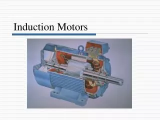
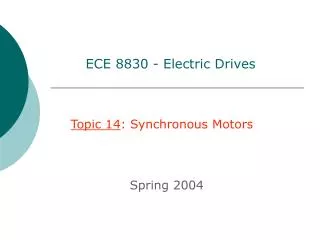
AC Motor • As in the DC motor case, a current is passed through the coil, generating a torque on the coil. Since the current is alternating, the motor will run smoothly only at the frequency of the sine wave. It is called a synchronous motor. More common is the induction motor, where electric current is induced in the rotating coils rather than supplied to them directly. One of the drawbacks of this kind of AC motor is the high current which must flow through the rotating contacts. Sparking and heating at those contacts can waste energy and shorten the lifetime of the motor. In common AC motors the magnetic field is produced by an electromagnet powered by the same AC voltage as the motor coil. The coils which produce the magnetic field are sometimes referred to as the "stator", while the coils and the solid core which rotates is called the "armature". In an AC motor the magnetic field is sinusoidally varying, just as the current in the coil varies.
Magnetic Force • The magnetic field B is defined from the Lorentz Force Law, and specifically from the magnetic force on a moving charge: The implications of this expression include: 1. The force is perpendicular to both the velocity v of the charge q and the magnetic field B. 2. The magnitude of the force is F = qvB sinθ where θ is the angle < 180 degrees between the velocity and the magnetic field. This implies that the magnetic force on a stationary charge or a charge moving parallel to the magnetic field is zero. 3. The direction of the force is given by the right hand rule. The force relationship above is in the form of a vector product.
Magnetic Force • The magnetic field B is defined from the Lorentz Force Law, and specifically from the magnetic force on a moving charge: • From the force relationship above it can be deduced that the units of magnetic field are Newton seconds /(Coulomb meter) or Newtons per Ampere meter. • This unit is named the Tesla. It is a large unit, and the smaller unit Gauss is used for small fields like the Earth's magnetic field. • A Tesla is 10,000 Gauss. • The Earth's magnetic field is on the order of half a Gauss.
Right Hand Rule • A useful mnemonic for visualizing the direction of a magnetic force as given by the Lorentz force law. • The diagrams above are two of the forms used to visualize the force on a moving positive charge. The force is in the opposite direction for a negative charge moving in the direction shown. One fact to keep in mind is that the magnetic force is perpendicular to both the magnetic field and the charge velocity, but that leaves two possibilities. The right hand rule just helps you pin down which of the two directions applies.
Right Hand Rule • The right hand rule is a useful mnemonic for visualizing the direction of a magnetic force as given by the Lorentz force law. • The diagrams above are two of the forms used to visualize the force on a moving positive charge. • The force is in the opposite direction for a negative charge moving in the direction shown. • One fact to keep in mind is that the magnetic force is perpendicular to both the magnetic field and the charge velocity, but that leaves two possibilities. • The right hand rule just helps you pin down which of the two directions applies. • For applications to current-carrying wires, the conventional electric current direction can be substituted for the charge velocity v in the above digram.