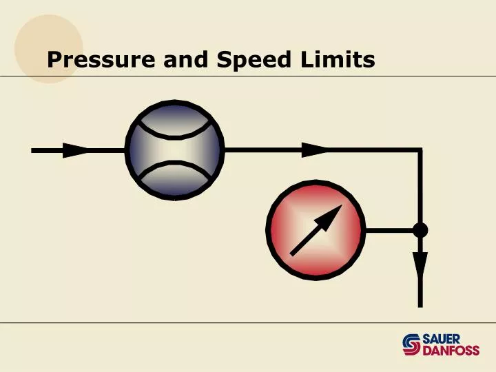

Pressure and Speed Limits
E N D
Presentation Transcript
Sauer-Danfoss Hydraulic Unit Design Pressure and Speed Ratings Fluid Quality Transmission Design Component Sizing Circuit Design Customer Machine Design Transmission Design Elements
Pressure & Speed Limits • Provide understanding of ratings and their relationship to expected life. BULLETIN PURPOSE BLN-9884
Key Concepts • Maximum and Rated pressure • Expected life • Maximum and Rated speed • Duty cycle
Load Vs Life Hi PRESSURE Low Long Short LIFE
Unit Life • Upper life limit • Rotating group • Bearings • Actual life • Heat • Contamination • Viscosity and lubricity of fluid
Max vs Rated Pressure MAXIMUM CONTINUOUS PRESSURE TIME
Pressure • Maximum Pressure • Highest intermittent pressure allowed • Determined by max. machine load demand • Less than 2% of total operating time • Continuous Pressure • Pressure expected when performing normal function • Normal input power, max. pump displacement • Weighted average
Consider Operating Conditions • Normal driving • High idle/no load • Overrunning load • Must know something about the frictional characteristics of engine
Swashplate Units Bent Axis (Series 51) Speed Ratings If Above Continuous, Contact Sauer-Danfoss Not always block lift first
Rated Speed • Life inversely proportional to speed • Highest speed recommended at full power • Highest speed for normal life • Varies with angle • Must always check Maximum speed limit
Maximum Speed • Highest operating speed permitted • Risk immediate failure if exceeded • May loose driveline power if exceeded • Highest negative power (downhill braking) • Catalog ratings…: • pumps: always reflect maximum swashplate angle • fixed motors: always reflect maximum swashplate angle • variable motors: both maximum and minimum angle are published
Design Speed Considerations • Full power • Full braking • Prime mover speed change • Pump drive ratios • Tolerance and drift of engine governors • Hydraulic unit volumetric losses • Tolerance in hydraulic unit displacement
Maximum Speed Considerations • Maximum motor operating speeds must be determined and compared to Maximum speed limits. • For vehicle propel drives this usually occurs during down-hill braking conditions. • Another severe condition is zero delta pressure at high engine idle speed.
Drive Design Finalization • Operating parameter check • Pressures < recommended limit • Speeds < recommended limit • Expected life achieved
Secondary Braking Insist thatyourcustomers provide a secondary means of braking on ALL vehicle propulsion systems!
Check Speed Limits • Check max angle limits of base units in catalog • Check charge pump limits • Check reduced displacement variable motor limits
Reduced Angle Speed Calculation • Swashplate Units: • Bent Axis Units: æ æ Speed at Speed at ö ö Tan Max Angle ç ç = ´ è ø è ø reduced angle maximum angle Tan Reduced Angle æ æ Speed at æ Speed at Sin Max Angle ö ö ö ç ç ç ÷ = ´ ø è è ø reduced angle maximum angle è Sin Reduced Angle ø Do not use speeds greater than the "Reduced Angle" speeds shown in the tables!
Rated Speed Maximum Speed rpm rpm Frame Size (Full Displ.) (Min. Displ.) (Full Displ.) (Min. Displ.) 080 3100 4000 6250 5000 110 2800 3600 5600 4500 160 2500 3200 5000 4000 250 2200 2700 4250 3400 Series 51 Speed Limits • Maximum Speed is the highest speed permitted.
Reduced Angle Motor Example • What is Rated speed limit of 51V110 at 22 degspeed @ 22 deg = speed @ 32 deg * (sin 32) (sin 22) = 2800 * (sin 32) (sin 22) = 3960 rpm • catalog reduced angle displacement max = 4500 rpm • use lesser of calculated vs. catalog, i.e. 3960 rpm
The Million Dollar Question D T U Y C C E Y L
Duty Cycle Definition • What is a Duty Cycle?
Cumulative Damage • Cumulative damage, or more precisely, cumulative fatigue damage, is the total damage to a component as a result of repeated cyclic loading. • Stress levels are not great enough to cause the component to fail under static loading. • Related to crack initiation within the material.
Duty Cycle Calculations • Calculation procedures vary. • Procedure has dramatic effect on predictions. • Sauer-Danfoss uses conservative procedures. • Competition: Compare calculation procedures.
What is Weighted Pressure? • Weighted pressure serves as a general indication of a duty cycle’s severity • The greater the weighted pressure, the lower the predicted life. • Of the three criteria for weighted pressure, this one is the least demanding.
Calculating Weighted Pressure • Weighted pressure equation: • Equation does not include any information concerning the shaft speed at each condition. • For duty cycles with equal weighted pressures, the life will be the same only if the speed at every condition is the same for both duty cycles.
Weighted Speed • Every duty cycle also has a weighted speed:
Weighted Speed • Equation for weighted speed is • Weighted Speed is not calculated using the traditional “weighted average” formula:
Duty Cycle Reduction • Knowing how to calculate the predicted life or the weighted pressure for a customer’s duty cycle is good thing to know, but… • How do I measure a duty cycle? • Usually too many conditions • Can’t test everything at once
Typical Pressure Distribution MAX LOAD HILL CLIMB NORMAL POWER PRESSURE LEVEL GROUND IDLE % Time
Combining duty cycles Max load 2% Hill climbing 20% 40% Normal power Life estimate 25% Level ground 13% Idle
Thank You • Questions?