Download
1 / 94
1.01k likes | 1.22k Views
Operation Manual. DXL. Running Order. How it works Your DXL parts and Accessories DXL radiation Safety Using your DXL Analyser Using your Analyser with your PC Advanced Settings Supervisor Examination. How XRF Works. How does XRF work?.

E N D
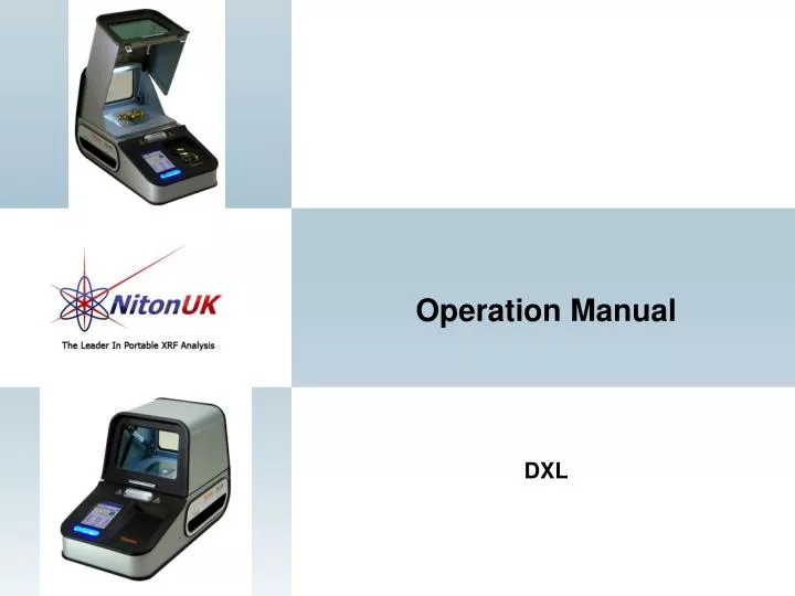
Operation Manual DXL
Running Order How it works Your DXL parts and Accessories DXL radiation Safety Using your DXL Analyser Using your Analyser with your PC Advanced Settings Supervisor Examination
How does XRF work? Each of the elements present in a sample produces a unique set of characteristic x-rays that is a "fingerprint" for that specific element. XRF analysers determine the chemistry of a sample by measuring the spectrum of the characteristic x-ray emitted by the different elements in the sample when it is illuminated by x-rays. These x-rays are emitted either from a miniaturized x-ray tube, or from a small, sealed capsule of radioactive material.
How does XRF work? • A fluorescent x-ray is created when an x-ray of sufficient energy strikes an atom in the sample, dislodging an electron from one of the atom's inner orbital shells. • The atom regains stability, filling the vacancy left in the inner orbital shell with an electron from one of the atom's higher energy orbital shells. • The electron drops to the lower energy state by releasing a fluorescent x-ray, and the energy of this x-ray is equal to the specific difference in energy between two quantum states of the electron.
XRF at work Atomic Level Process of Fluorescence Production
XRF at work When a sample is measured using XRF, each element present in the sample emits its own unique fluorescent x-ray energy spectrum. By simultaneously measuring the fluorescent x-rays emitted by the different elements in the sample, the XL2 can rapidly determine those elements present in the sample and their relative concentrations - in other words, the elemental chemistry of the sample.
Excitation Source Macro Level X-Ray Production
Technical Illustration of a NITON Analyzer DSP converts analog pulses to digital; sends to CPU. Digitized value represents original energy of characteristic X-Ray. Over measuring time, each element’s energy accumulated into a series of element/energy channels. Spectrum contains qualitative and quantitative information from the sample
Detector Si PIN Detector
DXL Battery and charger DXL Battery DXL Battery Charger
DXL Accessories Cont Prolene Windows USB Cable Small Spot Locator Battery Cover Rear Dust Cover Stylus
DXL Accessories Cont Software CD Quick Start Guide
Overview The Thermo Scientific Model Niton DXL series analyser contains an x-ray tube which emits radiation into a shielded sample chamber. The x-ray tube emits radiation only when a sample is being measured. During this time, indicator lights surrounding the analyser light up to alert personnel that the x-ray tube is on. The shielded sample chamber is designed to reduce radiation dose rates to less than 2.5 micro Sieverts (or equivalently 0.25 millirem) per hour at a 5 centimetre distance from any point along the surface of the analyser. The sample chamber is also designed with an interlock system so that the x-ray tube cannot be energized unless the sample chamber door is closed. The purpose of this interlock system is to prevent a person from placing any part of their body into the primary, unshielded x-ray beam. With the shielded and interlocked sample chamber, the Thermo Scientific Model Niton DXL series analyser can be operated safely with minimal programmatic and administrative controls. The following list summarizes the key safe use guidelines that all operators should be made aware of:
Overview Cont • • Operators should be provided basic radiation safety information. Consult with your local radiation Protection Advisor (RPA) to determine the specific operator training requirements for your needs. At a minimum, operators should read and understand the safety information in this manual. • • Where required by RPA, obtain authorization to use this analytical device. Authorization is typically granted in the form of a registration, license, certificate, or permit. Your local authority can be a valuable resource for safe use guidelines. • • Do not attempt to override interlocks or in any way interfere with their proper operation. • • The DXL analyser incorporates engineering controls that are designed to prevent access to the sample chamber during a measurement. Never place a part of your body in the sample chamber if the "X-RAY ON" indicator lights are on. • • Maintain the analyser in accordance with the instructions in this User's Guide. • • High voltage and high intensity x-ray beam hazards exist inside the instrument. Do not attempt to disassemble or service your analyser beyond the maintenance instructions described in this Resource Guide. Never remove parts or components except as described in this Resource Guide. Service must be performed at an authorized service centre. • • Use caution when lifting or moving the analyser to prevent strains or back injuries.
Time, Distance and Shielding • Radiation Protection Basics • Reasonable effort should always be made to maintain exposure to radiation as far below dose limits as is practical. This is known as the ALARA (As Low as Reasonably Achievable) principle. For any given source of radiation, three factors will help minimize your radiation exposure: Time, Distance, and Shielding. • Time • The longer you are exposed to a source of radiation the longer the radiation is able to interact in your body and the greater the dose you receive. Dose increases in direct proportion to length of exposure. • Distance • Intensity of radiation becomes weaker as it spreads out from a source since the same amount of radiation becomes spread over a larger area. Based on geometry alone, dose increases and decreases with an inverse-squared relation to your distance from the source of radiation (additional dose rate reduction comes from air attenuation). For example, the radiation dose one foot from a source is nine times greater than the dose three feet from the source. • Shielding • Shielding is any material that is placed between you and the radiation source. The more material between you and the source, or the denser the material, the less you will be exposed to that radiation. The sample chamber of the Thermo Scientific Model Niton DXL series analyser incorporates various forms of shielding.
Radiation Dose Rates • The Niton DXL Series analyser is designed to limit the radiation dose rate to no more than 2.5 micro Sieverts per hour at a 5 cm distance from any point along the surface of the instrument under worst case operating conditions. Worst-case operating conditions are as follows: • • X-ray tube voltage at its maximum of 45 tube kilovolts; • • X-ray tube current at its maximum of 0.1 tube milliamps; • • An attenuated primary x-ray beam - i.e. no sample present, or; • • A solid plastic sample present to maximize scatter radiation. • The dose rates shown in the following table were measured while the analyser was operating under these worst-case conditions. Each measured value represents the maximum dose rate measured over the general area described. A Thermo Scientific Model MicroRem LE dose rate meter (SN:9049 calibrated 3/29/2012) was used to perform these measurements. The measured values listed are net above background. The background at the time and location of measurement was 0.1 μSv per hour. • The dose rate meter has an estimated minimum detection limit of 0.1 μSv per hour. The measurements were performed on August 17, 2012.
Storage and Transportation • Storage • Regulations in some jurisdictions may require that you store your analyser in a secured area to prevent access, use, and/or removal by unauthorized individuals. Storage requirements may vary by location, particularly with regard to storage at temporary job sites or away from your primary storage location such as hotels and motels and in vehicles. You should contact your local Radiation Control Authority to identify the specific storage requirements in your jurisdiction. • Transportation • Transport of lithium ion batteries is regulated by most transport authorities. End-users should obtain additional information and training regarding the local requirements for transport of lithium ion batteries, as appropriate for the specific transport modes that may be used. In particular, for air transport, most jurisdictions have adopted the regulatory guidance published by the International Air Transport Association (IATA). These IATA regulations provide instructions for the safe transport of lithium ion batteries by air in Packing Instructions 965 (for batteries packed alone) and Packing Instruction 966 (for batteries packed with equipment). You will find additional information about lithium ion battery safety and transportation in the Start up Operations and Standard Maintenance Sections of this Resource guide. • It is recommended that you ship the Niton DXL in its original shipping container and foam to protect the sensitive measuring equipment inside the analyser.
Battery Installation and Charging Unscrew the captive screw on the battery door and remove the door. Grasp the cloth tag on the bottom of your analyzer’s battery and firmly pull the battery out into your hand.
Battery Installation and Charging Cont Place the old battery aside and slide the new battery into the cavity in the rear of the analyser. The battery is keyed, and will only insert fully one way. If it bottoms before it is fully inserted, remove the battery, turn it over top to bottom, and reinsert it. Press in until the battery clicks into place. Replace the battery door and screw in the captive screw.
Recharging The Battery Pack The battery pack is normally trickle charged in the analyser when the analyser is plugged in, but it is faster to use the battery recharger - especially if you normally use battery power a lot. Fully recharging a depleted battery pack in the charger takes approximately 2 hours. 1. Remove the battery pack from the analyser. 2. Place the battery pack upside down into the charger. The battery pack is keyed, and will only fit into the charger fully one way. If your battery pack is resting on the back of the charger rather than sliding all the way to the bottom, remove the battery pack, turn it around, and re-insert it into the charger. 3. The red light blinks when the charger needs a calibration. The red light is steadily on when the charger has a fault. 4. The blue light blinks when the charger is running a calibration. The blue light is steadily on when the calibration is complete. 5. The green light blinks when the charger is charging a battery. The green light is steadily on when the charging is complete.
Inspecting your analyser The LED Power and Safety Indicators The LED Power Indicators are located surrounding the Power and Trigger Buttons on the Control Panel. These LED Lights are on whenever your analyser is powered on. The LED Safety Indicators are located on the sides of your analyser, just above the Carrying Handles; on the rear of your analyser, just above the Port Cover; and surrounding the CoverRelease Button near the top edge of the Control Panel where it meets the Cover. These LED lights are on whenever a sample is being analysed or whenever a System Check is in progress. The Control Panel The control panel is located on the analyser’s front housing, directly below the Touch Screen. The control panel consists of a Power Button and a larger Trigger Button. Using the touch screen you may navigate through all of the analyser’s screens and menus. The Trigger Button to the right of the Power Button is used to initiate readings. The Power Button both controls the power to the analyser and serves as an "escape" button. When the Power Button is pushed and immediately released, it functions as an "escape", and brings you back to the Main Menu from the current screen in the menu system.
Replacing the Measurement Window CAUTION: Take every precaution to prevent damage to the solid beryllium surface of the tube and detector behind the analysis window. Both the x-ray tube and detector are located directly behind the analysis window and each has a small surface of solid beryllium or beryllium oxide. Beryllium-containing materials, in solid form and as finished parts, present no particular health hazard. However, exposure to the dust or fumes from beryllium metal or metal oxides has the potential to cause serious health effects. WARNING: Before you begin, cut off power to your analyser! WARNING: In the event that there is known or suspected damage to the solid beryllium surface of the tube or detector, the following precautions are recommended. Use latex or other disposable gloves for any handling or clean up of visible beryllium fragments or contamination. Collect fragments into a thick plastic bag, seal the bag tightly with adhesive tape, and affix a label clearly indicating “Danger Beryllium”. If there has been any inadvertent contact with skin, thoroughly wash affected skin area with soap and water before eating, drinking, or smoking. Contact your health and safety staff and/or Thermo Fisher Scientific customer support for further instruction if needed. Dispose of beryllium waste in accordance with all federal, state or local regulations. Remove the old Measurement Window from the bracket. Clean the Window area thoroughly, using a clean, guaranteed lint-free cloth and isopropyl alcohol. Measurement Window is Kapton - P/N 187-4280 CAUTION! Do not use fingers to press window into place! Use a smooth, hard surface such as back of tweezers.
Start up procedure To turn on the analyzer, depress the On/off/escape button on the control panel until the Touch Screen comes on. On startup, the screen will show by a Start Screen which will automatically count down from 4 to 0 in increments of one second. When the start up is complete, the Start Screen will be replaced by the Logon Screen. Tap anywhere on this screen to continue. The Logon Screen will be replaced by a Warning Screen, advising you that this analyser produces radiation when the lights are flashing. You must acknowledge this warning by selecting the Yes button before logging on. Selecting the No button will return you to the Logon Screen. Select your 4 digit security code, followed by the Enter button. The default password is 1-2-3-4
Start up procedure After you have completed the log on procedure, the word "USER" will appear on the bottom of the screen, then the Main Menu will appear. Note that security codes are editable. This will be covered in ‘advanced settings’. There we can change passwords and set User Privileges. Please Note - Your analyser will need to set the temperature of the detector to -25ºC before it can be used. If you attempt to use the analyser before this procedure the instrument will display the warning ‘Please wait, cooling detector’. This procedure will take no longer than 60 seconds once logged in and will remain stable until the analyser is powered down.
System check Every DXL analyser will have the ‘system check’ function. This function is an internal check to maintain the instruments fundamental parameters calibration, check tube output and detector resolution. This is an important operation to perform as over time the instruments detector can suffer from electronic drift slightly shifting the calibration curve. Running the ‘system check’ can keep the instruments calibration curve in line which will continue to provide the best possible results from the analyser.
System check Select the System Check Icon on the Main Menu to perform a system check. We recommend that you perform a system check once every working day, as part of your normal start up procedure. Click yes to continue the system check. Please make sure at this time there is nothing on the front of the instrument that could affect the reading. If you attempt to initiate a system check while the cover is open, a Safety Message will be displayed informing you the "Lid is open", and you will return to the Main Menu. While performing the system check, your screen will show a progress bar indicating the progress of the check. When it is done, the screen will show a 100% completion. If however there is an error message we advice you to call Niton UK Service on 01256 397860 or email service@nitonuk.co.uk
Calibrating the Touch Screen Select the Calibrate Touch Screen icon to re-calibrate the analyser's touch screen display. This procedure establishes the display boundaries for the touch screen interface.
Analyze mode and tools The Tools Menu can be accessed in two ways, and the options are different depending on the way you access it. The main Tools Menu is accessed by selecting the Analyze Icon from the Main Menu, then selecting the Tools button from the slide down window on the Ready to Analyze screen. From the main menu select analyze to go in to the testing mode for the instrument. From this mode you will be able to perform various tasks including taking an analysis, adding data and set averaging. The Tools Menu enables you to perform common data-related tasks such as printing and averaging readings. Select a task from the menu to initiate that task. The options available can vary depending on the selected mode.
AuDIT The AuDIT algorithm determines whether or not a surface is plated. AuDIT can detect plating as thick as 8mm. Since most plating is in the 2-3mm range, this can usually detect plated objects. Heavily plated objects with a plating greater than 8mm thick will read as Gold Plate Not Detected. AuDIT can be toggled on or off from your Tools Menu. This toggle is only available in Precious Metals Mode. Selecting the AuDIT:Off button will turn AuDIT on, and change the button to "AuDIT:On". Selecting the AuDIT:On button will turn AuDIT off, and change the button to "AuDIT:Off". AuDIT uses four separate tests run automatically to determine whether or not a sample is plated. 1. The first test is an iterative comparison of X-ray intensity signatures. This finds most examples of plating. 2. Nickel is often used as a pre-plate, and high proportions of Ni in a reading are a good indicator of plating. 3. Plating's often have a low Karat value when averaged with the substrate, so Karat values of less than 9 are flags indicating plating. 4. A Karat rating that is not one of the standard Karat percentages - within 0.5 karat of 9kt, 10kt, 14kt, 18kt, 22kt, or 24kt (referred to as Out of Plumb) - also strongly indicate that this is a plating. Only if the sample passes all four tests is it labelled Gold Plate Not Detected". This does not mean that there is no plating, but that the presence or absence of plating cannot be determined by the analyser. X-ray Intensity Hi Ni Low Karat Non-Std. Karat Rating
AuDITAdditional Methods of Plating Detection Analyze the item in several different areas Variance of more than 1-2% in Au content can be a positive indication that an item is plated. Look for identifying marks (hallmarks) Compare to your results. Discrepancies may indicate that an item is plated. Note: You may come across some Italian jewellery that has 18k gold plating over 14k gold. This is hallmarked as 14k or 585, but will likely show 16-17k on XRF. “Smell” the item A metallic, copper-like smell (similar to copper-based coins such as USA pennies) indicates the possible presence of a copper substrate under gold plating. Use a strong magnet A magnetic draw on the item may indicate a magnetic substrate under gold plating (gold alloys are not magnetic). As a final and last resort… analyze a spot, perform a deep file or grind, and then analyze the same spot again. A reduced gold content (more than 1-2%) indicates a thinning of the gold plating layer.
AuDITMessages If AuDIT is not enabled, a white on black message stating "AuDIT Disabled" will display on the Results Screen while in Precious Metals Mode. If AuDIT detects what looks like gold plating on the material, a black on red message stating "Gold Plate Probable" will display on the Results Screen. If AuDIT detects what may be gold plate, but isn't sure, a black on yellow message stating "Gold Plate Suspect" will display on the Results Screen. If AuDIT finds too much Nickel in the sample, a black on yellow message stating "High Ni Content" will display on the Results Screen. When AuDIT finds a Karat rating less than 8.5 in the sample, a black on yellow message stating "Low Karat" will display on the results Screen. If AuDIT detects what is either unplated gold or very thickly plated gold, a black on white message stating "Gold Plate Not Detected" will display on the Results Screen. When AuDIT finds a Karat rating other than the standard Karats, a black on yellow message stating "Non-Standard Karat" will display on the results Screen.
Using your analyser PREPARATORY TASKS 1.Turn the analyser on. Follow the screen instructions and “Log On” as the operator using either the default password or a custom one as designated by the user in an NDU file. See advanced settings for details. 2. Wait five (5) minutes before using the analyser, allowing the instrument electronics to stabilize. 3. Verify that the date is set properly for data tracking purposes. See advanced settings for details. 4. (Optional) Connect the analyser to a computer via the included USB cable. 5. During analysis and detector calibrations, it is important to ensure that the analyser is not exposed to strong electromagnetic fields, including those produced by computer monitors, hard drives, mobile telephones, walkie talkies, etc. Keep a minimum two (2) feet (0.7 meters) distance between the analyser and electronic devices. 6. From the Main Menu, select System Check icon then the "Yes" button. 6.1. System Check calibrates the detector and verifies it is operating to specifications. After starting the process, no further user interaction is required during this operation. When the instrument is finished performing the check, the unit will show “System OK”. If the analyser shows any other message displaying a fault contact Niton UK.
Using your analyser TAKING A MEASUREMENT Open the lid using the push button on the front of the lid. Place the item to be tested over the measurement window and close the lid. Use the camera to line up the item. Press the start/stop button to start the test and again to finish the test once you are happy with the result. Once the test is finished you can open the lid and take out the item. Opening the lid whilst the test is ongoing will end the test. GENERAL TESTING PROTOCOL The analyser will often display a correct alloy identification and accurate chemistry result before the above specified time interval. If the accuracy meets the user’s requirements, it is not necessary to measure for the full time. Longer measurements might be necessary if low concentrations of alloy elements must be determined. INSTRUMENT QC Measure the supplied calibration check sample AT LEAST once a shift. If correct, continue work. If incorrect, redo System Check and re-take the past 2 hours of results. UNDERSIZED OR NON-CONTACT SAMPLES (samples that do not make contact with or that do not fully cover the measurement aperture) For samples that do not fully cover the measurement aperture, increase the testing time by increasing the time in inverse proportion to the decrease in percentage of aperture covered. For example: a ring only covers ½ of the aperture, so increase the measurement time by two (e.g., from 10 to 20 seconds per filter for chemistry).
Averaging Forward Enables you to average different readings together from this analysis forward. Select the Avg Forward button to initiate future sample averaging. Avg Forward will set up an automatic personal averaging protocol to be followed until your analyser is shut down, or this feature is disabled. To begin, select the number of readings you want to average from the virtual numeric keypad. Your analyser will calculate an average reading after that number of tests, and continue this pattern until stopped. For example, if you select 3 on the virtual keypad, the analyser will automatically calculate, average, and store a reading for every three tests you take, storing the individual readings along the way. The range number is selected using a virtual numeric keypad on your analyser similar to the keypad used for login. Select the digits in the range number from the keypad, then select the E button to enter the number. The C button will clear all, and the “<“ button will clear the last digit entered. The average will automatically be displayed.
Avg Back (Alt) Enables you to average different readings together from this analysis backward. Select the Avg Back option to initiate backwards sample averaging. Avg Back will take the number of readings you select and average their analytical results. The range is counted from the last reading backward by the number of readings selected. If your last reading was #15, selecting 3 would average readings #13, 14, and 15. The average is calculated, displayed, and stored into memory as the next sequential reading number, in this case, #16. The range number is selected using a virtual numeric keypad on your analyser similar to the keypad used for login. Select the digits in the range number from the keypad, then select the E button to enter the number. The C button will clear all, and the “<“ button will clear the last digit entered. The average will automatically be displayed.
Data management Viewing Data Use the Data Screen to view previously taken test result readings. When the View Data icon is selected, the Results screen of your most recent test is shown on the Touch Screen. Using the buttons on the control panel, you may view different readings or additional data for individual readings. Your analyser will display the standard screen analysis. Selecting the Complete List icon will display a complete scrolling elemental chemistry listing. Each press of the Down Button scrolls the screen down to the next element. You can also use the scroll bar along the right side to scroll or page through the elements. Scrolling Down Through the Complete Listing of Elements Selecting the Left Arrow icon (<--) on your analyser's touch screen will display the previous reading, or if the first reading is currently displayed, the last reading. Selecting the Right Arrow icon (-->) on your analyser's touch screen will display the next reading, or if the last reading is currently displayed, the first reading in memory. Your analyser can store up to 10,000 readings. You can also look at the complete x-ray spectra for each reading stored in the analyser's memory.
Erasing Data Select the Erase Readings icon to erase all accumulated test readings from your analyser. Selecting the Erase Readings icon will bring up a confirmation screen asking you “Are you sure?” with options to select “YES” or “NO”. Selecting the Yes Button will erase all test reading data from your analyser. Selecting the No Button will return you to the Erase Menu. Note - We recommend that you download all your readings into an NDT file for recording purposes before erasing all data.
PC Requirements We recommend the following system configuration for Niton Data Transfer (NDT) The installation program installs NDT and NDTr. You may install the files in any directory on your PC.
Installing NDT 1. Close all the programs that you have open on your PC. 2. Insert the CD into the CD-ROM drive. If the installation program starts automatically, follow the instructions on the screen. If the installation program does not start, go to the next step. 3. Double-click My Computer. 4. Double-click the Compact Disc icon: 5. Double-click the Setup Application icon. 6. Follow the instructions on the screen.
Starting NDT Software 1. Click the Start button. 2. Select Programs. 3. Select Thermo Niton. 4. Click NDT.
Connecting the XRF Analyser to Your PC 1. Insert the Standard USB connector on the USB cable into a USB port on your computer. 2. Open the Port Cover on the XRF Analyser. 3. Turn on the analyser and insert the mini USB connector on the USB cable into the USB port. 4. Upon initial installation, insert the NDT disk located behind the foam in your case. Follow the prompts and install the USB driver located on the disk.
Connecting the XRF Analyser to Your PC (cont) The USB cable 1. Insert the NDT CD and close out any dialogue box that pops up. The driver is located on this disk. 2. Click on “Control Panel” and locate the “Device Manager”. If it is not available direct under “Control Panel”, look under “System and Security” then “System”. 3. Open “Device Manager” 4. Plug in instrument using the USB cable provided 5. Message will appear “Device Driver Software Not Successfully Installed”
Connecting the XRF Analyser to Your PC (cont) 6. In “Device Manager”, “Unknown Device” will appear under “Other Devices” 7. Right click on “Unknown Devices”; select “Update Driver Software” 8. Click on “Browse My Computer for Driver Software”
Connecting the XRF Analyser to Your PC (cont) 9. Click “Browse” button; select CD drive or the location of the driver if you are not installing from the NDT CD (recommended). 10. Click “OK” 11. Click “Next” 12. A Security Dialog Box will appear. Select “Install This Driver Software Anyway?” 13. Driver will install; close out. 14. Insert the Standard USB connector on the USB cable into a USB port on your computer.