Download

1 / 19
190 likes | 354 Views
Electronics. Underpinning Knowledge Questions. What are the specific safety practices and procedures that you need to observe when assembling and testing electronic circuits? ( To include: any specific legislation, regulations or codes of practice for the activities, equipment or materials.).

E N D
Electronics Underpinning Knowledge Questions
What are the specific safety practices and procedures that you need to observe when assembling and testing electronic circuits?(To include: any specific legislation, regulations or codes of practice for the activities, equipment or materials.) • Is the test equipment in good condition? • Are the test leads for the equipment in a safe condition, no nicks or breaks in the insulation? • Have you tested the test equipment on a known working electrical supply before connecting it to your circuit? • Has the test equipment been recently calibrated? • Have you been trained to carry out this task? Do you have the skills? • Are you wearing the correct PPE to complete this task? • Are you practising safe soldering techniques, perhaps you could describe a safe and effective soldering procedure? • Are the tools you are using to form and trim the component leads maintained in a safe condition? • If you are making a PCB, are you following the correct procedures?
What are the hazards associated with assembling and testing electronic circuits and how can they be minimised? (Such as: heat, toxic fumes, spilled / splashed chemicals / solder, static electricity, using sharp instruments for stripping cable insulation, connecting clips / probes into circuits.) What are the hazards associated with assembling and testing electronic circuits and how can they be minimised? (Such as: heat, toxic fumes, spilled / splashed chemicals / solder, static electricity, using sharp instruments for stripping cable insulation, connecting clips / probes into circuits.) What are the hazards associated with assembling and testing electronic circuits and how can they be minimised?(Such as: heat, toxic fumes, spilled / splashed chemicals / solder, static electricity, using sharp instruments for stripping cable insulation, connecting clips / probes into circuits.) • Are you using ventilation next to your circuit? • Are you wearing eye protection when making PCB boards and trimming component leads? • Have you selected the correct components and checked them against a data sheet? • How can you minimize the risk of static damage to a circuit containing integrated components? • Is the PPE you are wearing suitable for the job? • Have the tools you are using been maintained in a safe condition? • Are you using a heat shunt when soldering delicate components such as transistors? • Have you tested a circuit with the correct test equipment to ensure it electrically dead prior to handling it? • Perhaps you could describe the correct procedure for setting up a multimeter to test for current, voltage and resistance (each one is different) • Are testing the circuit with the correct voltage and power supply? • Have you tested for short circuits and open circuits (perhaps you could describe the difference between them)
Why is it important to wear appropriate protective clothing and equipment?Why is it important to keep the work area safe and tidy? • To protect your clothes? • To protect your skin and eyes, for example repeated exposure to some chemicals can cause dermatitis and cancer • To protect your lungs and respiratory system from dangerous fumes and gases • Are you using a barrier cream to minimize skin contact with the chemicals used to make the PCB’s • If you have an accident whilst making PCB’s and were not using the correct PPE, do you think you will have grounds for compensation? • If someone else has an accident because of your negligence, do you think they will have grounds to seek compensation from you? • Does a messy and untidy workplace assist you in making circuits? • Is a messy and untidy workplace likely to contribute to accidents? • Whose responsibility is it to ensure the workplace is in a safe and tidy condition? • If you spot an unsafe practice, what would you do? • Is it your responsibility to report hazards to an appropriate person?
What precautions do you need to take to prevent electrostatic discharge (ESD) damage to circuits and sensitive components?(Such as: use of earthed wrist straps, anti-static mats, special packaging and handling areas.) • Use wrist straps that can be earthed • Wear anti static boots and clothing that is less likely to cause a build up of static charge • Stand on anti static mats when assembling circuits
How do you use and extract information in relation to work undertaken?(To include: circuit diagrams, block and schematic diagrams, equipment manuals, data sheets, test procedures and instructions [to include: symbols and conventions to appropriate BS or ISO standards].) • Read circuits diagrams and list all of the components required • Check component values using charts, British standards and data sheets • Check component tolerances once again using charts and data sheets • Check component symbols against BS EN60617 • Recognize that not every drawing you encounter will use BS circuit symbols, for example some circuits use ANSI symbols (American National Standards Institute) • Use the circuit diagram to plan a layout for your circuit taking into account the size and proximity of various components • Check your circuit design against the layout for every stage of the design process
How do you recognise, read the values and identify polarity and any other orientation requirements for all electronic components being used in the assemblies?(Such as: capacitors, resistors, inductors, diodes, transistors, integrated circuit chips, and other discrete through-hole or surface-mounted components.) • Check resistor values using the resistor colour code • Check resistor tolerance values using the colour code and double check with a multimeter • Use pin out diagrams to identify the function of pins on integrated circuits e.g. Power , ground, input and output • Use data sheets to identify the polarity of the terminals on diodes • Describe the difference between through hole and surfact mount components (such as size, reading component values and the absence of component leads on surface mount components) • Check capacitor values using a chart, internet resources or data sheets • Check polarity dependant components are connected the right way around (longer leg is connected to positive) • Describe how the polarity of electrolytic capacitors and LED’s can be established
How do you check that components meet the required specification / operating conditions?(Such as: values tolerance, current carrying capacity, voltage rating, power rating, working temperature range.) • Check information from the circuit diagram which should contain the required information • Check data sheets to find the current carrying capacity of components • Check data sheets for working temperature range • Often working voltages are stamped on components such as capacitors • Power rating: How do you check the power rating of a resistor? • What is the power rating the general purpose resistors used in the laboratory? (.25 Watt)
What are the basic principles of operation of the electronic circuits being assembled? • The amplifier takes a small input signal from a source such as an ipod or mp3 player and reproduces the signal at its output. The signal at the output is much larger than the input (thats what amplify means) which allows it to drive a loudspeaker. • The fuse tester can also be used to test the continuity of a circuit. It uses a NOR gate to detect whether the fuse is good. If the fuse is good the NOR gate gives an output voltage of 5 volts. This voltage is used to switch on a transistor which drives a 555 timer and an LED. The 555 timer gives out a high pitched tone if the fuse is working and the LED lights up. • The H bridge stepper motor control circuit uses 8 transistors to control the current through both phases of the stepper motor. The current must be fed to the stepper motor in the correct sequence in order for it to run forwards and backwards. A microcontroller is programmed to switch the transistors on and off. The entire circuit is powered through a bridge rectifier and voltage regulator which gives power to the microcontroller. The stepper motor power is taken from a point directly before the regulator as +12 volts smoothed DC.
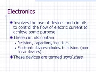
What is the purpose of the individual modules/components within the circuits? • Each component will fulfil a given purpose within the circuit • The circuit function will rely on each component being correctly chosen and connected to the circuit • Often circuits can be broken down into a series of function blocks or modules For example the amplifier circuit has: • A mixing stage • A preampifier • Volume control • A power amplifier • An output stage The continuity tester circuit has: • A voltage regulator to fix the working voltage at 5 volts • A logic circuit to test the continuity of a circuit • A signal generator stage to give an audible signal when continuity is present
How and why is circuit protection equipment used? • Circuit protection equipment is there to protect the user, the circuit and the environment • Circuit faults can lead to overheating which left untended can cause fires • The two most common circuit faults which present danger to people are short circuits and earth faults Short circuits: • Bypass components in the circuit either by bad design, poor soldering, faulty components or moisture • This means more current is drawn from the power supply • More current = more power = more heat • Under certain circumstances the circuit can draw so much current that the insulation begins to break down • Fuses and Residual Current Devices (RCD) prevent this happening by cutting the power supply to the circuit Earth Faults: • When a live conductor comes into contact with the metal housing of an appliance you have an earth fault • This means the housing will be electrically live, if you touch it then current will flow through you to ground • Earth Current Leakage Breakers (ECLB’s) and RCD’s can be used to protect people from earth faults
What are the methods of mounting and securing electronic components to various surfaces? • Use of heat sinks and heat shunts to prevent damage to sensitive components • You can find some information on surfact mount techniques here • You are already familiar with manual soldering methods, keep soldering tip clean and tinned etc • Mechanical fixing methods include the use of chocolate block and wire wrapping
What are the methods for attaching markers/labels to components to assist with identification? • You can use masking tape • Coloured electrical tape • Colour coded tags • Coloured cable ties Marking and identification techniques are essential when maintainingand upgrading circuits, for more information you can visit here
Why should you use BS7671/IEEE wiring and othe regulations, when selecting wires and cables and when carrying out tests on electronic circuits? It is difficult to get hold of the 17th edition book without buying it. However the most important reasons for using the standards and regulations above can be listed as: • It is a legal obligation to ensure you are complying with the given standards • Complying with the standards means you are testing your circuits in the safest way possible • The standards are there to ensure that circuits are built and tested using suitable components and cables • The standards give information of cables and conductors so that you are able to select ones which are safe to use with the current you circuit will be conducting • So that you don’t over engineer your circuits designs and builds, choosing the correct cable for the job in not only safe, it is also cost effective.
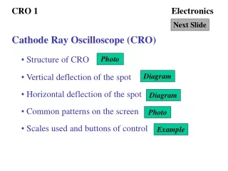
How do you care for, handle and use electronic test and measuring equipment?How do you check that test equipment is safe to use?How do you check that test equipment is suitable for the tests you are to carry out and can cover the range and values you are to measure? • Check the equipment is physically sound with no signs of mechanical or electrical damage before use • Check the equipment has been tested and calibrated, normal practice is to test the equipment each gear, there should be a sticker on the equipment detailing the date and outcome of the last test • Always make sure that the equipment is suitable for the job, don’t use equipment that doesn’t have the range to measure your circuit. For example there is no point trying to measure an input voltage of 20 volts if your meters range only goes up to 10 volts. • Make sure you are trained to carry out the tests • Always replace test equipment carefully after use, make sure it is switch off and leads are disconnected • Always test equipment on a known supply before carrying out a live test (known as a functional test) • If in doubt ask a qualified person • You can also check the manual/datasheet for the equipment in question
How do you connect equipment to an approved power supply and where appropriate signal source? • Always make sure the power supply is switched off before connecting to a circuit • Always make sure the signal source is switched off before connecting to a circuit • If the power supply is a variable type, make sure it is set up to the correct voltage and current before connecting • Check the signal is the correct frequency and amplitude before connecting • Always connect the ground clip or wire first • Always disconnect the ground clip or wire last
How do you make adjustments to circuit components? • Only certain components can be adjusted such as variable resistors, potentiometers, variable capacitors and inductors • Adjustments can be made under live conditions, you should be using an anti static wrist strap and an insulated screwdriver
How do you make adjustments to circuit components? Once you have decided a component is faulty: • Disconnect power from the circuit • Use test equipment to ensure that the circuit is electrically dead (all capacitors discharged etc) • Identify the component type and value using either the schematic or visual inspection • Carefully desolder and remove the component • Replace and resolder
What are the fault finding techniques to be used when equipment fails to operate correctly? • Carefully check the type and value of each component against the values given on the schematic • Check all polarity dependant components are connected the correct way around • Check the power supply is connected correctly and the correct voltage for the circuit is applied • Visually check all of the soldering tracks and joints to ensure there are no short circuits • Manually ‘pull test’ each component to ensure it is securely soldered to the board • With the power supply disconnected, use a multimeter to measure the resistance between power and ground • Check the continuity between all power points and check the continuity between all ground points • With the power supply connected check for the correct voltage at all of the supply points • Specific fault finding methods that can be used are half split and input to output