Download
1 / 23
230 likes | 310 Views
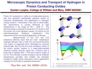
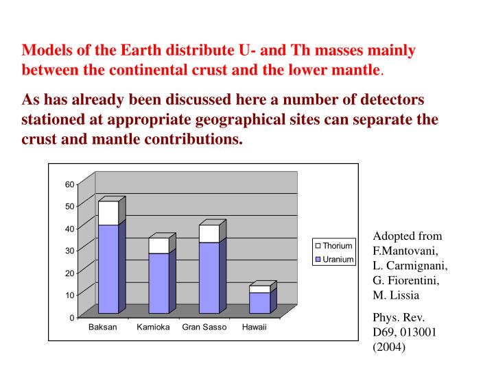
Models of the Earth distribute U- and Th masses mainly between the continental crust and the lower mantle . As has already been discussed here a number of detectors stationed at appropriate geographical sites can separate the crust and mantle contributions.

E N D
Models of the Earth distribute U- and Th masses mainly between the continental crust and the lower mantle. As has already been discussed here a number of detectors stationed at appropriate geographical sites can separate the crust and mantle contributions. Adopted from F.Mantovani, L. Carmignani, G. Fiorentini, M. Lissia Phys. Rev. D69, 013001 (2004)
Can Radiogenic Heat Sources inside the Earth be located by their Anti Neutrino incoming Directions? G. Domogatsky, V. Kopeikin, L. Mikaelyan, V. Sinev
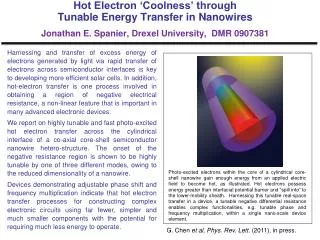
Here we analyze directional separation of e signals arriving from the crust and the lower mantle with only one detector. Crust Upper mantle Lower mantle Geoneutrinos from the Crust and the Lower Mantle enter the detector from different directions. Liquid core Hard core
NEUTRON DETECTION We consider CH2 , = 0.8 g/cm3 Liquid Scintillation Detector and e + p => e+ + n Geoneutrino detection reaction. The Geoneutrino signature is delayed coincidence between the positron and neutron signals.
Positron spectrum boosted by two 511 keV annihilation quanta is shown below: 90Sr-90Y calibration source Counts per MeV U+Th Th Positron energy released, MeV
NEUTRINO DIRECTIONS Parallel geoneutrino beam (along Z-axis) This geometry was studied earlier at CHOOZ with reactor antineutrinos. 1) Neutron initial direction is strongly correlated with the incoming e direction. En = 2.5 MeV qmax 26º pe qen pn pn
Angular distribution of reaction (1) neutrons relative to the incident geoneutrino direction weighted with the reaction cross section 8000 4000 0 cos qnn = 0.967 0.8 0.9 1 cos qnn
2). In first few collisions with scintillator atoms the memory is partially conserved and neutron is displaced from the reaction point in + Z directions. After 7 - 8 collisions the memory is lost and neutrons slow down and diffuse symmetrically around the displaced center. N=1 N=3 Z, cm <Z>=1.32 cm <Z>=0.66 cm N=5 N=8 Z, cm <Z>=1.58 cm <Z>=1.72 cm X, cm X, cm
CONCLUSIONS We present a first attempt to analyze directions of a multidirectional low energy flux. In this attempt only two geoneutrino sources have been taken into account: the continental crust and lower mantle. We haven’t analyzed perturbations due to possible fluctuations of U and Th concentrations in the detector’s immediate vicinity. Clearly more work is needed to come to more accurate results.
At this preliminary stage of analysis we can summarize the results as follows: Present understanding of radiogenic sources and their distribution in the Earth’s reservoirs is based on a shaky ground of cosmogenical and geochemical arguments with an obvious deficit of direct experimental evidence Information obtained with one 30-kton target mass detector using directional separation of incoming geoneutrino flux is useful but limited: it can give only some indications against the orthodox Earth’s model predictions, or can provide it’s rough confirmation. More definite information can be obtained only with ~ 4 times larger detector
Later neutrons diffuse and are captured symmetrically around the displaced center. For parallel e beam the average neutron displacement is calculated as: dz = 1.72 cm now we find: < Renx > = < Reny > 0 /N1/2 , < Renz > = 1.72 /N1/2, N is the number of detected reaction (1) events and is vector R component’s Gaussian dispersion. Dispersion 20 cm is considerably larger than the displacement dZ = 1.7 cm and thuse statistics (N) should be sufficiently large.
ASSUMING NOW N = 2500 and = 20cm (as in the CHOOZ experiment) we get: dZ = 1.7 04 cm Thus neutron displacement can be found at 4 st. deviation level (which is exactly the CHOOZ result).
Geoneutrinos from the lower mantle We generate 105 MC events and find the average displacement dLM: dLM = 1.20 cm
With ~30 kton target mass 4000 geoevents can be accumulated in 5 years of data taking. N = 4000 is considered here as maximally thinkable events sample. dLM = 1.20 cm 20 / 40001/2 = 1.2 0.32
GEONEUTRONOS from the CRUST Here we consider hypothetical case where continental crust source forms a uniform 6000 km diameter and 40 km thick circular region centered around the geoneutrino detector The vertical component of the flux is small here and the neutron displacement is also small: dCr = < Renz > 0.29 cm /N1/2
e from the Crust and the Lower Mantle The average displacement of neutron cloud in the vertical direction is given by the expression: dLM+Cr = LM dLM + (1 – LM)dCr/N1/2, where dLM = 1.2 cm, dCr = 0.29cm and LM = FLM / (FLM + FCr) is the lower mantle fraction in the total geoneutrino incoming flux; N = 4000, the maximal achievable events sample considered here, /N1/2 = 0.32 cm.
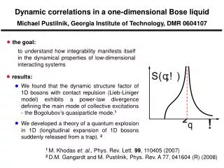
1.5 1 0.5 0 dz, cm 0 0.2 0.4 0.6 0.8 1 aLM Vertical displacement of neutron clouddLM +Cr vs relative contribution LMof lower mantle to the total (crust + lower mantle) geoneutrino flux (solid line). Shaded is the (68% CL) uncertainty region, the dark gray area between vertical lines represents model’ prediction for detector installed in BNO.
One can see that separation method considered here is not very sensitive. Only sufficiently large displacements dLM+Cr, larger than 1 cm if found, can indicate contradiction to the predictions of the orthodox Earth’s model. In case experiment favours lower displacements, and thus indicates low contribution of the mantle geoneutrino flux, the dominant role of the crust geoneutrinos predicted by the model can roughly be confirmed. Only with much larger number of collected events (N ~ 2104 ) and therefore with much larger detector more definite conclusions could be obtained.
P.S.Detector calibrations Detection of small displacements discussed above requires adequate calibration procedures. While usual method, based on inserting neutron- and gamma sources into the fiducial volume can and should be exploited, the use of sufficiently more strong source is highly desirable.
We propose for calibration purposesamovable ~ 1 MCi 90Sr-90Y antineutrino source. 90Sr (T1/2 = 28.6 yr) decays to the ground state of 90Y(Emax = 2.28 MeV, T1/2 = 64h). If installed at the distance of 30 m from the 30 kton detector center, the source can generate about 2105 events of reaction (1) per year.
Two circumstances make this source attractive: First, it will irradiate the detector with flux of known intensity, known energy spectrum in the geoneutrino energy range and of known angular structure 90Sr-90Y calibration source Counts per MeV At a distance of 30 m there will be ~ 200 000 events/(year·30 kt) Th U+Th Positron energy released, MeV
and, second, the sources are produced commercially and used to supply heat for Radioisotope Thermoelectric Generators (RTGs) We note that proposed calibration method could also be used in other low energy experiments employing large liquid scintillation detectors.
For each neutrino event positron and neutron capture positions are reconstructed and positron –neutron vector ReNi is found: ReNi.= RNi – Rei The Reconstruction procedure is based on light and (or) time signals from PMTs. Neutrino direction is found be neutron displacement in thee direction Information of neutrino incoming directions is derived from vector ReNi. analysis.