Download
1 / 50
500 likes | 628 Views
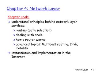
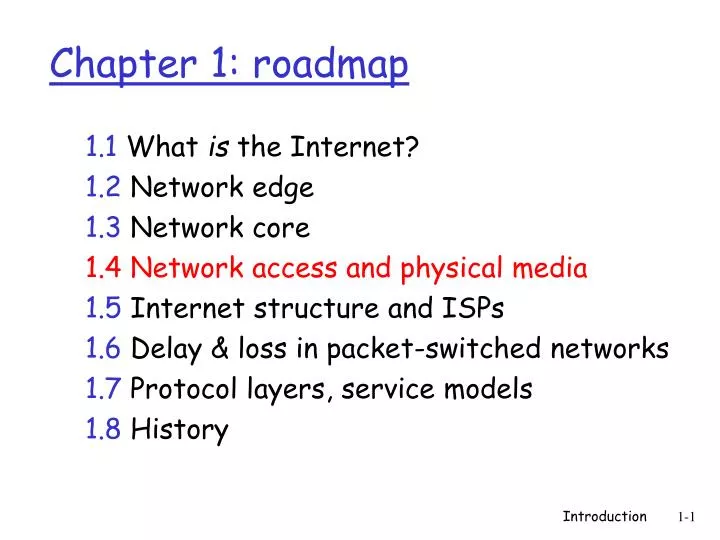
Chapter 1: roadmap. 1.1 What is the Internet? 1.2 Network edge 1.3 Network core 1.4 Network access and physical media 1.5 Internet structure and ISPs 1.6 Delay & loss in packet-switched networks 1.7 Protocol layers, service models 1.8 History.

E N D
Chapter 1: roadmap 1.1 What is the Internet? 1.2 Network edge 1.3 Network core 1.4 Network access and physical media 1.5 Internet structure and ISPs 1.6 Delay & loss in packet-switched networks 1.7 Protocol layers, service models 1.8 History Introduction
Q: How to connect end systems to edge router? residential access nets institutional access networks (school, company) mobile access networks Keep in mind: bandwidth (bits per second) of access network? shared or dedicated? Access networks and physical media Introduction
Dialup via modem up to 56Kbps direct access to router (often less) Can’t surf and phone at same time: can’t be “always on” Residential access: point to point access • ADSL: asymmetric digital subscriber line • up to 1 Mbps upstream (today typically < 256 kbps) • up to 8 Mbps downstream (today typically < 1 Mbps) • FDM: 50 kHz - 1 MHz for downstream 4 kHz - 50 kHz for upstream 0 kHz - 4 kHz for ordinary telephone Introduction
HFC: hybrid fiber coax asymmetric: up to 1Mbps upstream, up to 10 Mbps downstream network of cable and fiber attaches homes to ISP router shared access to router among home issues: congestion, dimensioning deployment: available via cable companies, e.g., MediaOne, Comcast, RCN Residential access: cable modems Introduction
Residential access: cable modems Diagram: http://www.cabledatacomnews.com/cmic/diagram.html Introduction
Cable Network Architecture: Overview Typically 500 to 5,000 homes cable headend home cable distribution network (simplified) Introduction
Cable Network Architecture: Overview cable headend home cable distribution network (simplified) Introduction
server(s) Cable Network Architecture: Overview cable headend home cable distribution network Introduction
C O N T R O L D A T A D A T A V I D E O V I D E O V I D E O V I D E O V I D E O V I D E O 5 6 7 8 9 1 2 3 4 Channels Cable Network Architecture: Overview FDM: cable headend home cable distribution network Introduction
company/univ local area network (LAN) connects end system to edge router Ethernet: shared or dedicated link connects end system and router 10 Mbs, 100Mbps, Gigabit Ethernet deployment: institutions, home LANs happening now LANs: chapter 5 Company access: local area networks Introduction
shared wireless access network connects end system to router via base station aka “access point” wireless LANs: 802.11b (WiFi): 11 Mbps wider-area wireless access provided by telco operator 3G ~ 384 kbps Will it happen?? WAP/GPRS in Europe router base station mobile hosts Wireless access networks Introduction
Typical home network components: ADSL or cable modem router/firewall/NAT Ethernet wireless access point Home networks wireless laptops to/from cable headend cable modem router/ firewall wireless access point Ethernet (switched) Introduction
Bit: propagates betweentransmitter/rcvr pairs physical link: what lies between transmitter & receiver guided media: signals propagate in solid media: copper, fiber, coax unguided media: signals propagate freely, e.g., radio Twisted Pair (TP) two insulated copper wires Category 3: traditional phone wires, 10 Mbps Ethernet Category 5 TP: 100Mbps Ethernet Cat 5e/6: 1Gbps Ethernet Physical Media Introduction
Coaxial cable: two concentric copper conductors bidirectional baseband: single channel on cable legacy Ethernet broadband: multiple channel on cable HFC Physical Media: coax, fiber Fiber optic cable: • glass fiber carrying light pulses, each pulse a bit • high-speed operation: • high-speed point-to-point transmission (e.g., 5 Gps) • low error rate: repeaters spaced far apart; immune to electromagnetic noise Introduction
signal carried in electromagnetic spectrum no physical “wire” bidirectional propagation environment effects: reflection obstruction by objects interference Physical media: radio Radio link types: • terrestrial microwave • e.g. up to 45 Mbps channels • LAN (e.g., WaveLAN) • 2Mbps, 11Mbps, 54Mbps • wide-area (e.g., cellular) • current/old: 10’s Kbps • 3G: hundreds of kbps • satellite • up to 50Mbps channel (or multiple smaller channels) • 270 msec end-end delay • geosynchronous vs. LEOS Introduction
Chapter 1: roadmap 1.1 What is the Internet? 1.2 Network edge 1.3 Network core 1.4 Network access and physical media 1.5 Internet structure and ISPs 1.6 Delay & loss in packet-switched networks 1.7 Protocol layers, service models 1.8 History Introduction
roughly hierarchical at center: “tier-1” ISPs (e.g., UUNet/MCI, Level3, Sprint, AT&T, Cable&Wireless, Qwest, etc.), national/international coverage treat each other as equals NAP Tier-1 providers also interconnect at public network access points (NAPs) Tier-1 providers interconnect (peer) privately Internet structure: network of networks Tier 1 ISP Tier 1 ISP Tier 1 ISP Introduction
Tier-1 ISP: e.g., Sprint Sprint US backbone network Introduction
“Tier-2” ISPs: smaller (often regional) ISPs E.g., Verizon, Fastnet, etc. Connect to one or more tier-1 ISPs, possibly other tier-2 ISPs NAP Tier-2 ISPs also peer privately with each other, interconnect at NAP • Tier-2 ISP pays tier-1 ISP for connectivity to rest of Internet • Tier-2 ISP is customer of tier-1 provider Tier-2 ISP Tier-2 ISP Tier-2 ISP Tier-2 ISP Tier-2 ISP Internet structure: network of networks Tier 1 ISP Tier 1 ISP Tier 1 ISP Introduction
“Tier-3” ISPs and local ISPs last hop (“access”) network (closest to end systems) Tier 3 ISP local ISP local ISP local ISP local ISP local ISP local ISP local ISP local ISP NAP Local and tier- 3 ISPs are customers of higher tier ISPs connecting them to rest of Internet Tier-2 ISP Tier-2 ISP Tier-2 ISP Tier-2 ISP Tier-2 ISP Internet structure: network of networks Tier 1 ISP Tier 1 ISP Tier 1 ISP Introduction
a packet passes through many networks! Tier 3 ISP local ISP local ISP local ISP local ISP local ISP local ISP local ISP local ISP NAP Tier-2 ISP Tier-2 ISP Tier-2 ISP Tier-2 ISP Tier-2 ISP Internet structure: network of networks Tier 1 ISP Tier 1 ISP Tier 1 ISP Introduction
Chapter 1: roadmap 1.1 What is the Internet? 1.2 Network edge 1.3 Network core 1.4 Network access and physical media 1.5 Internet structure and ISPs 1.6 Delay & loss in packet-switched networks 1.7 Protocol layers, service models 1.8 History Introduction
packets queue in router buffers packet arrival rate to link exceeds output link capacity packets queue, wait for turn packet being transmitted (delay) packets queueing (delay) free (available) buffers: arriving packets dropped (loss) if no free buffers How do loss and delay occur? A B Introduction
1. nodal processing: check bit errors determine which output link transmission A propagation B nodal processing queueing Four sources of packet delay • 2. queuing • time waiting at output link for transmission • depends on congestion level of router Introduction
3. Transmission delay: R=link bandwidth (bps) L=packet length (bits) time to send bits into link = L/R 4. Propagation delay: d = length of physical link s = propagation speed in medium (~2x10⁸ m/sec) propagation delay = d/s transmission A propagation B nodal processing queueing Delay in packet-switched networks Note: s and R are very different quantities! Introduction
Cars “propagate” at 100 km/hr Toll booth takes 12 sec to service a car (transmission time) car~bit; caravan ~ packet Q: How long until caravan is lined up before 2nd toll booth? Time to “push” entire caravan through toll booth onto highway = 12*10 = 120 sec Time for last car to propagate from 1st to 2nd toll both: 100km/(100km/hr)= 1 hr A: 62 minutes toll booth toll booth Caravan analogy 100 km 100 km ten-car caravan Introduction
Cars now “propagate” at 1000 km/hr Toll booth now takes 1 min to service a car Q:Will cars arrive to 2nd booth before all cars serviced at 1st booth? Yes! After 7 min, 1st car at 2nd booth and 3 cars still at 1st booth. 1st bit of packet can arrive at 2nd router before packet is fully transmitted at 1st router! See Ethernet applet at AWL Web site toll booth toll booth Caravan analogy (more) 100 km 100 km ten-car caravan Introduction
Nodal delay • dproc = processing delay • typically a few microsecs or less • dqueue = queuing delay • depends on congestion • dtrans = transmission delay • = L/R, significant for low-speed links • dprop = propagation delay • a few microsecs to hundreds of msecs Introduction
R=link bandwidth (bps) L=packet length (bits) a=average packet arrival rate Queueing delay (revisited) traffic intensity = La/R • La/R ~ 0: average queueing delay small • La/R -> 1: delays become large • La/R > 1: more “work” arriving than can be serviced, average delay infinite! Introduction
“Real” Internet delays and routes • What do “real” Internet delay & loss look like? • Traceroute program: provides delay measurement from source to router along end-end Internet path towards destination. For all i: • sends three packets that will reach router i on path towards destination • router i will return packets to sender • sender times interval between transmission and reply. 3 probes 3 probes 3 probes Introduction
“Real” Internet delays and routes traceroute: gaia.cs.umass.edu to www.eurecom.fr Three delay measurements from gaia.cs.umass.edu to cs-gw.cs.umass.edu 1 cs-gw (128.119.240.254) 1 ms 1 ms 2 ms 2 border1-rt-fa5-1-0.gw.umass.edu (128.119.3.145) 1 ms 1 ms 2 ms 3 cht-vbns.gw.umass.edu (128.119.3.130) 6 ms 5 ms 5 ms 4 jn1-at1-0-0-19.wor.vbns.net (204.147.132.129) 16 ms 11 ms 13 ms 5 jn1-so7-0-0-0.wae.vbns.net (204.147.136.136) 21 ms 18 ms 18 ms 6 abilene-vbns.abilene.ucaid.edu (198.32.11.9) 22 ms 18 ms 22 ms 7 nycm-wash.abilene.ucaid.edu (198.32.8.46) 22 ms 22 ms 22 ms 8 62.40.103.253 (62.40.103.253) 104 ms 109 ms 106 ms 9 de2-1.de1.de.geant.net (62.40.96.129) 109 ms 102 ms 104 ms 10 de.fr1.fr.geant.net (62.40.96.50) 113 ms 121 ms 114 ms 11 renater-gw.fr1.fr.geant.net (62.40.103.54) 112 ms 114 ms 112 ms 12 nio-n2.cssi.renater.fr (193.51.206.13) 111 ms 114 ms 116 ms 13 nice.cssi.renater.fr (195.220.98.102) 123 ms 125 ms 124 ms 14 r3t2-nice.cssi.renater.fr (195.220.98.110) 126 ms 126 ms 124 ms 15 eurecom-valbonne.r3t2.ft.net (193.48.50.54) 135 ms 128 ms 133 ms 16 194.214.211.25 (194.214.211.25) 126 ms 128 ms 126 ms 17 * * * 18 * * * 19 fantasia.eurecom.fr (193.55.113.142) 132 ms 128 ms 136ms trans-oceanic link * means no response (probe lost, router not replying) Introduction
Packet loss • queue (aka buffer) preceding link in buffer has finite capacity • when packet arrives to full queue, packet is dropped (aka lost) • lost packet may be retransmitted by previous node, by source end system, or not retransmitted at all Introduction
Chapter 1: roadmap 1.1 What is the Internet? 1.2 Network edge 1.3 Network core 1.4 Network access and physical media 1.5 Internet structure and ISPs 1.6 Delay & loss in packet-switched networks 1.7 Protocol layers, service models 1.8 History Introduction
Networks are complex! many “pieces”: hosts routers links of various media applications protocols hardware, software Question: Is there any hope of organizing structure of network? Or at least our discussion of networks? Protocol “Layers” Introduction
ticket (complain) baggage (claim) gates (unload) runway landing airplane routing ticket (purchase) baggage (check) gates (load) runway takeoff airplane routing airplane routing Organization of air travel • a series of steps Introduction
ticket (complain) baggage (claim) gates (unload) runway landing airplane routing ticket (purchase) baggage (check) gates (load) runway takeoff airplane routing airplane routing Organization of air travel: a different view Layers: each layer implements a service • via its own internal-layer actions • relying on services provided by layer below Introduction
Layered air travel: services Counter-to-counter delivery of person+bags baggage-claim-to-baggage-claim delivery people transfer: loading gate to arrival gate runway-to-runway delivery of plane airplane routing from source to destination Introduction
airplane routing airplane routing airplane routing Distributed implementation of layer functionality ticket (complain) baggage (claim) gates (unload) runway landing airplane routing ticket (purchase) baggage (check) gates (load) runway takeoff airplane routing arriving airport Departing airport intermediate air traffic sites Introduction
Why layering? Dealing with complex systems: • explicit structure allows identification, relationship of complex system’s pieces • layered reference model for discussion • modularization eases maintenance, updating of system • change of implementation of layer’s service transparent to rest of system • e.g., change in gate procedure doesn’t affect rest of system • layering considered harmful? Introduction
application: supporting network applications FTP, SMTP, HTTP transport: host-host data transfer TCP, UDP network: routing of datagrams from source to destination IP, routing protocols link: data transfer between neighboring network elements PPP, Ethernet physical: bits “on the wire” application transport network link physical Internet protocol stack Introduction
Each layer: distributed “entities” implement layer functions at each node entities perform actions, exchange messages with peers network link physical application transport network link physical application transport network link physical application transport network link physical application transport network link physical Layering: logical communication Introduction
E.g.: transport take data from app add addressing, reliability check info to form “datagram” send datagram to peer wait for peer to ack receipt analogy: post office network link physical application transport network link physical application transport network link physical application transport network link physical application transport network link physical data data data ack Layering: logical communication transport transport Introduction
network link physical application transport network link physical application transport network link physical application transport network link physical application transport network link physical data data Layering: physical communication Introduction
M M H H H H H H H H H H H H t t t n l n l t n t n t M M M M application transport network link physical application transport network link physical M M Protocol layering and data Each layer takes data from above • adds header information to create new data unit • passes new data unit to layer below source destination message segment datagram frame Introduction
Chapter 1: roadmap 1.1 What is the Internet? 1.2 Network edge 1.3 Network core 1.4 Network access and physical media 1.5 ISPs and Internet backbones 1.6 Delay & loss in packet-switched networks 1.7 Internet structure and ISPs 1.8 History Introduction
1961: Kleinrock - queueing theory shows effectiveness of packet-switching 1964: Baran - packet-switching in military nets 1967: ARPAnet conceived by Advanced Research Projects Agency 1969: first ARPAnet node operational 1972: ARPAnet demonstrated publicly NCP (Network Control Protocol) first host-host protocol first e-mail program ARPAnet has 15 nodes Internet History 1961-1972: Early packet-switching principles Introduction
1970: ALOHAnet satellite network in Hawaii 1973: Metcalfe’s PhD thesis proposes Ethernet 1974: Cerf and Kahn - architecture for interconnecting networks late70’s: proprietary architectures: DECnet, SNA, XNA late 70’s: switching fixed length packets (ATM precursor) 1979: ARPAnet has 200 nodes Cerf and Kahn’s internetworking principles: minimalism, autonomy - no internal changes required to interconnect networks best effort service model stateless routers decentralized control define today’s Internet architecture Internet History 1972-1980: Internetworking, new and proprietary nets Introduction
1983: deployment of TCP/IP 1982: SMTP e-mail protocol defined 1983: DNS defined for name-to-IP-address translation 1985: FTP protocol defined 1988: TCP congestion control new national networks: Csnet, BITnet, NSFnet, Minitel 100,000 hosts connected to confederation of networks Internet History 1980-1990: new protocols, a proliferation of networks Introduction
Early 1990’s: ARPAnet decommissioned 1991: NSF lifts restrictions on commercial use of NSFnet (decommissioned, 1995) early 1990s: Web hypertext [Bush 1945, Nelson 1960’s] HTML, HTTP: Berners-Lee 1994: Mosaic, later Netscape late 1990’s: commercialization of the Web Late 1990’s – 2000’s: more killer apps: instant messaging, peer2peer file sharing (e.g., Napster) network security to forefront est. 50 million host, 100 million+ users backbone links running at Gbps Internet History 1990, 2000’s: commercialization, the Web, new apps Introduction
Covered a “ton” of material! Internet overview what’s a protocol? network edge, core, access network packet-switching versus circuit-switching Internet/ISP structure performance: loss, delay layering and service models history You now have: context, overview, “feel” of networking more depth, detail to follow! Introduction: Summary Introduction