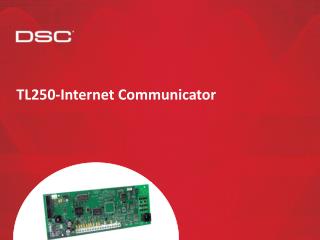
TL250-Internet Communicator
TL250-Internet Communicator. Compatibility. Specifications. 250mA @12 VDC current draw 12 VDC input voltage Size: 3.25” × 5.25” (8.3 × 13.3)cm Operating Temperature: 32°-122°F (0°-49°C) Output Protocols: UDP/IP 10/100 BaseT half duplex Input Protocols: PC-Link (SIA format)

TL250-Internet Communicator
E N D
Presentation Transcript
Specifications • 250mA @12 VDC current draw • 12 VDC input voltage • Size: 3.25” × 5.25” (8.3 × 13.3)cm • Operating Temperature: 32°-122°F (0°-49°C) • Output Protocols: UDP/IP 10/100 BaseT half duplex • Input Protocols: PC-Link (SIA format) • Connectors: 4-pin header for the PC-Link and RJ-45 for Ethernet • Network: Ethernet LAN/WAN 10 BaseT, 10/100 BaseT or 100 BaseT • Downloading Support for PC4020 V3.3+/PC5020/PC1616/PC1832/PC1864 Control Panel: using DLS2002 and/or DLS2002 System • Administrator software • 4 digital inputs (can be increased to 12 using the PC5108) • Capable of sending alarm messages to 2 e-mail addresses
Board Overview PC Link Header to Panel Network Connection LED1 = Speed Status (ON = 100Mbps Connection OFF = 10Mbps Connection) LED2 = Activity Status (Displays Network Traffic RX/TX ) LED3 = Link Status (ON = Ethernet Present OFF = Ethernet Absent) 12VDC and GND Keybus to PC5108 Zone 1 - 4
Status LED Flashes Per sec.TL250 Status 1/3 Flash -Normal 1 Flash -Network Absent 2 Flash -Invalid Account 3 Flash -Receiver 1 Absent 4 Flash -Panel Absent 5 Flash -Inputs Alarms 6 Flash -FTC 1 7 Flash -PC5108 Absent 8 Flash -PC5108 Tamper 9 Flash -FTC 2 10 Flash -Key switch Arm 11 Flash -Remote Programming 12 Flash -Local Programming 13 Flash -Receiver #2 Absent
Connecting to the panel Connect PC-Link Cable Connect Network Cable 12VDC and GND
Programming Requirements • Static IP Address Programming • IP address of TL250 • IP address of Subnet Mask • IP address of DRL3IP • IP address of Network Gate • Account Number Dynamic IP Address Programming IP address of DRL3IP Account Number Example IP Address 192.168.0.99 255.255.255.0 209.202.119.7 192.168.0.1 0000001234
Programming (4020) Enter installer programming by pressing *8 followed by your installers code Select (00) <> System Area Press [*] to select System Area Select (00) <> Installer Opt’s Scroll over to Communicator and press [*] Scroll over to Comms Toggles and press [*] Select (04) <> Communicator Scroll until you see an option for the T-Link and press [*] to enable the option Select (01) <> Comms Toggles Select Toggle <> T-Link Enable Y
Programming continued… Select (01) <> Comms Toggles Press [#] to Exit Comms Toggles Scroll over to T-Link Module and press [*] Enter a 3 digit Section number followed by the entry Select (06) <> T-Link Module Select Entry # Ent 001-999 _
Programming continued… Select Entry # Ent 001-999 001 Enter IP Address 192.168.000.099 Enter the 12 digit IP Address of the TL250 followed by [#]. This should be given to you by your IT department.ENTER ALL ZERO’S FOR DHCP. Select Entry # Ent 001-999 002 Enter IP Address 000.000.000.000 Enter the 12 digit Subnet Mask followed by [#]. This should be given to you by your IT department.DO NOT PROGRAM FOR DHCP Enter the 6 digit account number for the TL250 followed by [#] of the TL250. This should be given to you by your central station. If you account is only 4 digits, enter 00 00 00 then the 4 digit account number Select Entry # Ent 001-999 003 Select Entry #1 Enter 00-FF 00 Enter the 12 digit IP Address of the DRL3IP followed by [#]. This should be given to you by your central station. Select Entry # Ent 001-999 007 Enter IP Address 000.000.000.000 Enter the 12 digit IP Address of the Gateway followed by [#]. This should be given to you by your IT department.DO NOT PROGRAM FOR DHCP Select Entry # Ent 001-999 008 Enter IP Address 000.000.000.000
Programming continued… Select Entry #1 Enter 00-FF 99 Enter [55], wait 30 seconds then press [#] all the way out of programming. Select Entry # Ent 001-999 999 Enter [999] to default the TL250 Optional - If Network Supervision is Required… Enter [01] to enable Supervision for Network Supervision.DO NOT PROGRAM FOR UN-SUPERVISED ACCOUNTS Select Entry # Ent 001-999 023 Enter Hex Data 00 Optional - If 128 AES Encryption is Required… Enter the FIRST 16 hexadecimal digits of the Encryption key. This is provided to you by your central station. Select Entry # Ent 001-999 004 Enter Hex Data 0000000000000000 Enter the LAST 16 hexadecimal digits of the Encryption key. This is provided to you by your central station. Select Entry # Ent 001-999 005 Enter Hex Data 0000000000000000
4020 Panel Programming Ref# 0004000000 Panel Tel number = CAAA Ref# 000400XX01 Comms Format = SIA FSK Ref# 000401 Auto SIA = Y Ref# 000400XX02 Dialer Directions = Alarms Y etc… Ref# 000300 DLS Enabled* = Y *if downloading is required
Programming Power Series • TL250 Programming: • Section 382 opt 5 PC-Link Active = enabled • All TL250 programming in section [851] • [001] –TL250 IP address, [002] –Subnet Mask, [003] -6 digit account number, [007] –DRL3IP IP address, [008] –Gateway • [999], enter a 55 to restart (00 to default)
Programming Power Series • Power Series Communication Programming: • Section 301 Panel Tel number = DCAA • Section 350 Comms Format = SIA FSK • Section 381 opt 3 Auto SIA = enabled • Section 401 opt 1 DLS Enabled* = enabled • *if downloading is required
DLS 2002 Software • DLS2002 Programming a panel via TL250 • Ensure the DLS2002 TL250 Driver is installed (DLS2002 T-Link II Driver.exe)
DLS 2002 Software • Programing the panel Via DLS2002 and TL250: • Change Modem to TCP/IP Select TCP IP then click OK
DLS 2002 Software • DLS2002 Programming a panel via TL250 • Enter the TL250’s IP address when an account is created or edited under account properties IP address of TL250
DLS2002 Programming a panel via TL250 • Upload/download control panel as usual
Thank you for your timeFor future assistance, feel free to contact me atgharman@dsc.com