Download
1 / 12
120 likes | 236 Views
PRS/SPD static envelop, assembly and installation. Detector layout Static envelop along the beam Detector structure Module box and fibre routing Supermodule design and assembly LED monitoring cabling structure SM installation. Detector layout. Dimension H x W (m2) 7.7x7.65

E N D
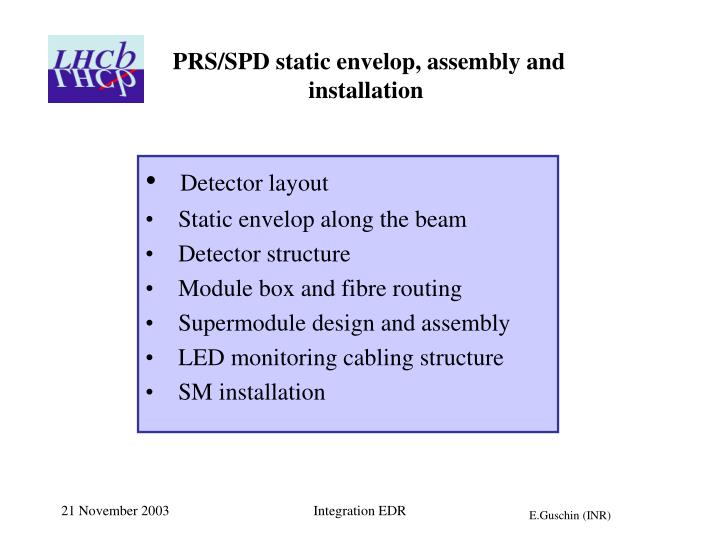
PRS/SPD static envelop, assembly and installation • Detector layout • Static envelop along the beam • Detector structure • Module box and fibre routing • Supermodule design and assembly • LED monitoring cabling structure • SM installation Integration EDR
Detector layout • Dimension H x W (m2) 7.7x7.65 • Active area H x W (m2)6.2 x 7.65 Along beam 18 cm • Weight Lead 10 t 414 modules 1.6 t 16 supermodules 16 x 250 kg Integration EDR
Static envelop along beam After the lead thickness has been changed to 2.5X0, the gap between lead and detector also has been decreased. The other dimensions are not changed since EDR. Integration EDR
PRS/SPD detector structure Integration EDR
Number of modules and tiles Modules number: 444 Tiles number: 14144 Integration EDR
Module boxes and WLS fibers routing Fibers routing is essentially the same for inner, middle and outer modules: Integration EDR
The clear fibres layout The fibres layout will match the electronics mapping. The orientation of optical connectors is “up” and “down” to avoid cable loops. Integration EDR
LED monitoring: cables LED trigger: 96 splitters for 752 drivers Control voltage Integration EDR
Supermodule frame design Frame of supermodule It consists of two Al C-beams and one I-beam connected by perforated Al plates. The tooling for supermodule assembly will be designed and constructed in INR. Assembly of supermodule including installation of modules, clear fibre bundles and cabling will be done in CERN Integration EDR
Assembly of SM • The assembly of supermodule will start with frame assembly. Then the frame will be fixed on the supporting cradle to allow the further assembly with modules in horizontal position. • In the beginning, the optical and monitoring cables will be installed from one side of the frame, then the cradle is rotated and the module boxes will be installed on another side. The supporting tools for the assembly and storage will be designed and constructed in INR. The supporting cradle. Integration EDR
Assembly of SM Electronics will be installed on the supporting plates attached to the ends of SM frame structure. Integration EDR
SM installation • General scheme is as it was in TP except the installation will be done without electronics. • SM will be attached to neighbors, geometrical alignment is necessary at 4 points (2 – top; 2-bottom) Integration EDR