Download
1 / 14
140 likes | 251 Views
Modifications to Simulation Scenarios and Calibration Process. Date: 2014-07-01. Authors:. Overview. Proposed changes to simulation scenario details Discussions surrounding PHY calibration process led to identification of some unspecified details, as well as parameters requiring modification.

E N D
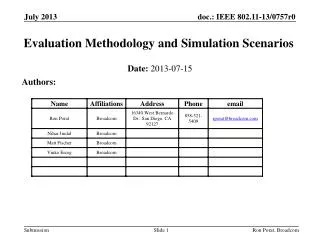
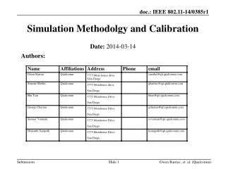
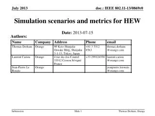
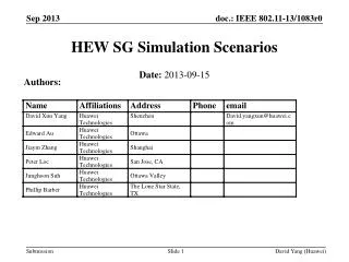
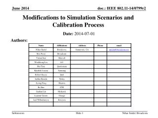
Modifications to Simulation Scenarios and Calibration Process Date: 2014-07-01 Authors: Nihar Jindal, Broadcom
Overview • Proposed changes to simulation scenario details • Discussions surrounding PHY calibration process led to identification of some unspecified details, as well as parameters requiring modification Nihar Jindal, Broadcom
Antenna Gains • Current antenna gains are +2 dBi for AP and -4 dBi for STA • Antenna gain reflects antenna efficiency and directionality • Directionality is strongly dependent on link type (AP-STA, STA-STA, AP-AP) and implementation, so preference is to not include any directionality. • Proposal: Change antenna gains to +0 dBi for AP’s, -2 dBi for STAs • Reflects lower efficiency at STA devices vs. AP devices, but not any directivity Nihar Jindal, Broadcom
TX Power • Current TX powers are: • Proposal: Unified power levels of 15 dBm per STA antenna and 20 dBm per AP antenna, for all scenarios • STA power limit also applies to STA device (i.e., phone) acting as soft AP Nihar Jindal, Broadcom
Carrier Frequency For the sake of simplicity we propose to ignore the minor path loss variation due to different carrier frequencies for different channels within a band (e.g., lower 5G versus upper 5G) Proposal: For all channels within the 2.4 GHz band, the carrier frequency used to determine path loss shall be set to 2.4e9. Similarly, the carrier frequency shall be set to 5e9 for all channels within the 5GHz band Nihar Jindal, Broadcom
Wall Loss for Scenarios 1 and 2 • Scenarios 1 and 2 specify loss per wall, but do not explicitly indicate how diagonally separated walls are to be treated • Proposal: total # walls = # walls in x-direction + # walls in y-direction • i.e., diagonally separated apartments are considered to be separated by 2 walls Nihar Jindal, Broadcom
Path Loss and Fading Model for Scenario 2 • Currently 11nD and 11nB are listed as options for channel model, with 7 dB per office wall • 11nB and 11nD path loss models only differ in breakpoint distance: 5m vs 10m. 10m breakpoint appears more reasonable for a large office setting • 11nD fading model designed for a large office • Proposal: • 11nD path loss model (exponent of 2 up to breakpoint distance of 10m, exponent of 3.5 beyond), still with 7 dB per office wall • 11nD NLOS multipath model for all links, with iid log-normal shadowing (5 dB standard deviation) per link Nihar Jindal, Broadcom
Path Loss and Fading Model for Scenario 3 • Currently 11nB, 11nD, and ITU InH listed as options for channel model • 11nB and 11nD path loss models only differ in breakpoint distance: 5m vs 10m. 10m breakpoint appears more reasonable for a large office setting. • ITU InH model may not be consistent with scenario • Was designed for inter-site distance of 60m, compared to inter-site distance down to 17.3m for scenario • Uses LOS up to 18 meters, and has 0.5 probability of LOS even for large distances • 11nD fading model designed for a large indoor space. • Proposal: • 11nD path loss model (exponent of 2 up to breakpoint distance of 10m, exponent of 3.5 beyond) • 11nD NLOS multipath model for all links, with iid log-normal shadowing (5 dB standard deviation) per link Nihar Jindal, Broadcom
Minimum AP-STA distance • Scenarios 3 and 4 have a minimum x-y distance from AP of 1m and 10m respectively • Minimum x-y distance to AP should be modeled only if physically motivated, e.g., assumption that AP tower prevents STAs from being directly underneath tower • Minimum distance should be used in PL formulas to avoid negative path loss and to prevent unreasonably high RX powers • Proposal: • Remove 1m minimum x-y distance for S3 • Distance-based PL always based on 3-D distancewith minimum distance of 1 meter: • PL(3-D distance) = max(PL at 1 meter, PL for 3-D distance) Nihar Jindal, Broadcom
User dropping for scenarios 3 and 4, with reuse 1 • Process for dropping STAs not precisely described for scenarios 3 and 4 • RSSI-based association means STAs do not necessarily associate to closest AP • Option 1: Get exact # of associated STAs per AP • Drop STA randomly in 19 cell area and do RSSI based association • If associated AP already has specified # of STAs, then throw away STA; else associate to that AP • Repeat until every AP has correct # of STAs • Option 2: Variable # of associated STAs per AP, with average # equal to value in scenario document • Drop all STAs in 19 cell area, and do RSSI based association per STA • Each AP can have different # of associated STAs • Found that option 2 can lead to large variability in terms of # of STAs per AP • Will likely require large # of drops in order to get different simulation results to match • Distribution of RX power to associated AP same with either option 1 or 2 • Proposal: • Adopt option 1 for scenarios 3 and 4 • RSSI association performed based on distance-based path loss + loss + shadowing + antenna gain, but not on multipath Nihar Jindal, Broadcom
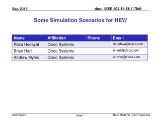
BSS BS BSS BSS BSS BSS BSS BSS BSS BSS BSS BSS BSS BSS BSS BSS BSS BSS BSS User dropping for scenario 3, reuse3 Nihar Jindal, Broadcom • Two options for dropping STAs in reuse 3 version of scenario 3: • Option 1: drop STAs in full 61 cell area, perform RSSI-based association to one of 61 AP’s, only keep STAs that associate to one of 19 reuse3 cells. Repeat process until have desired # of STAs per 19 reuse3 cells. • Option 2: drop STAs uniformly in 19 reuse3 cells, perform RSSI-based association to one of 19 reuse 3 AP’s. Repeat process until have desired # of STAs per 19 reuse3 cells. • Option 1 is consistent with an actual reuse3 deployment in which STA associates to any AP. • Investigation showed that using option 2 rather than option 1 changes distribution of RX power and STA locations • Proposal: Adopt option 1 for reuse 3 version of scenario 3
System Simulation Calibration Details • Further detail on a few points regarding System Simulation Calibration section of 802.11-14/0571 • Proposal: All calibration simulations shall be conducted in the 5 GHz band with 80 MHz channels (channelization specified within each scenario) • Proposal: Clarify that transmit power for Box 1 is the per-antenna power • Box1 of system simulation calibration (in 571r2) is based on long-term path loss (distance-based path loss + shadowing + wall/floor/penetration loss), and should correspond to single antenna transmission by all devices • Proposal: Specify CCA level of -70 dBm for Box 2, Test 3, and that CCA is measured across the entire bandwidth. • Value chosen to provide an intermediate level of interference • Proposal: Clarify that there is no notion of an un-associated STA (i.e., user that cannot bi-directionally sustain minimum MCS) for the purpose of calibration Nihar Jindal, Broadcom
Summary of Proposed Changes • Antenna gains for all scenarios: +0 dBi for AP’s and -2 dBi for STAs • TX power levels for all scenarios: 15 dBm per STA antenna and 20 dBm per AP antenna • Carrier frequency used in path loss formulas: 2.4e9 for all channels within the 2.4G band, 5e9 for all channels within the 5G band • # Walls for Scenarios 1 and 2 = # of walls in the x-direction plus # of walls in the y-direction • Scenario 2 channel model • 11nD path loss model (exponent of 2 up to breakpoint distance of 10m, exponent of 3.5 beyond), with 7 dB per office wall • 11nD NLOS multipath model for all links, with iid log-normal shadowing (5 dB standard deviation) per link • Scenario 3 channel model • 11nD path loss model (exponent of 2 up to breakpoint distance of 10m, exponent of 3.5 beyond) • 11nD NLOS multipath model for all links, with iid log-normal shadowing (5 dB standard deviation) per link • Remove minimum x-y distance of 1 meter from scenario 3, and for all scenarios distance-based path loss evaluated based on the maximum of 1 meter and the actual 3-D distance? • STA dropping process for scenarios 3 and 4 with reuse 1 • Drop STA randomly in 19 cell area and do RSSI based association (RSSI association performed based on distance-based path loss + loss + shadowing + antenna gain, but not on multipath) • If associated AP already has specified # of STAs, then throw away STA; else associate to that AP • Repeat until every AP has correct # of STAs • STA dropping process for scenarios 3 with reuse 3 • Drop STAs in full 61 cell area, perform RSSI-based association to one of 61 AP’s, only keep STAs that associate to one of 19 reuse3 cells which have fewer than the specified # of associated STAs. Repeat process until have desired # of STAs per 19 reuse3 cells. • Calibration process: • All calibration simulations in 5 GHz band with 80 MHz channels • Add clarification that transmit power for Box 1 is the per-antenna power • For Box 2 test 3, use CCA level of -70 dBm with CCA measured across the entire bandwidth. • Add clarification that there is no notion of an un-associated STA for the purpose of calibration Nihar Jindal, Broadcom
Straw Poll Do you agree to the changes specified in slides 3-13? Nihar Jindal, Broadcom