Welding Representation
Welding Representation. Chapter 22. Objectives. Describe the various welding processes Draw the common welding symbols Dimension a welding drawing using standard ANSI welding notations. Objectives (cont.).

Welding Representation
E N D
Presentation Transcript
Welding Representation Chapter 22
Objectives • Describe the various welding processes • Draw the common welding symbols • Dimension a welding drawing using standard ANSI welding notations
Objectives (cont.) • Identify and draw a fillet weld, groove weld, back weld, spot weld, seam weld, projection weld, and flash weld • Describe the use of welding symbols in CAD drawings
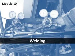
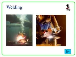
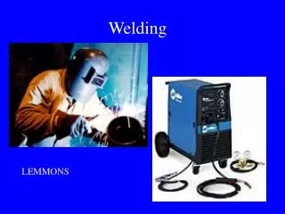
Welding Processes • The principal methods of welding are: • Gas welding • Arc welding • Resistance welding
Standard Symbols • Welding drawings are a special type of assembly drawing as weldments are composed of a number of separate pieces fastened together as a unit • Joints are all shown as they would appear before welding
Welding Symbols • The items that can be specified in a welding symbol are: • Type of weld • Process • Depth of bevel, size or strength for some weld types • Groove weld size • Finishing designator • Contour
Welding Symbols • Cont. • Groove angle • Root opening • Length of weld • Number and pitch of welds • Whether the weld is to be field welded • All around indicator • Which side of the material is to be welded
Types of Welded Joints • There are five basic types of welded joints: • Butt joint • Corner joint • T-joint • Lap joint • Edge joint
Types of Welds • There are four types of arc and gas welds: • Back or backing weld • Fillet weld • Plug or slot weld • Groove weld
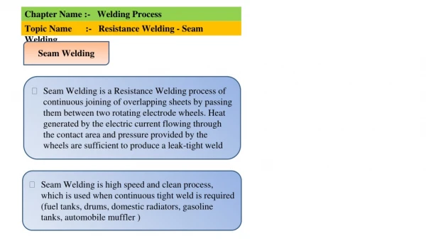
Types of Welds • The four basic resistance welds are: • Spot weld • Projection weld • Seam weld • Flash or upset weld
Welding Symbols • The basic element of the symbol is the “bent” arrow • The arrow points to the joint where the weld is to be made • Attached to the reference line, or shank, is the symbol for the desired weld
Fillet Welds • The usual fillet weld has equal legs
Surface Welds • The surface weld symbol indicates a surface to be built up
Flash and Upset Welds • Flash and upset weld symbols have no arrow-side or other-side significance
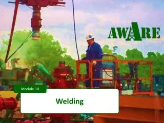
Welding Applications • Welding is often cheaper when only one or a few identical parts are required • Welding is also suitable for large structures that are difficult or impossible to fabricate entirely in a shop
Welding Templates • Welding templates can simplify drawing welding symbols by hand • They have all the forms needed for drawing the arrow, weld symbols, and supplementary symbols
Computer Graphics • Welding symbol libraries available in CAD and allow for rapid application of accurate, uniform symbols that are in compliance with standards