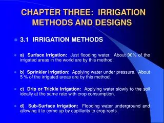
Irrigation Troubleshooting:
Irrigation Troubleshooting:. What does it take to be an “Irrigation Troubleshooter”?. An Electrician A Plumber An Electronics Technician An Irrigation Technician A Laborer ALL OF THE ABOVE. The 7 components of an irrigation system that we need to be concerned with:. • Water Supply

Irrigation Troubleshooting:
E N D
Presentation Transcript
What does it take to be an “Irrigation Troubleshooter”? An Electrician A Plumber An Electronics Technician An Irrigation Technician A Laborer ALL OF THE ABOVE
The 7 components of an irrigation system that we need to be concerned with: • Water Supply • Backflow Preventer • Main Line • Electric Valves • Lateral Lines • Heads • Controller
When a customer comes in or calls with an irrigation problem, what do you do?
What is malfunctioning? Is it the controller, valves, heads, sensors, etc.? Has anyone been working in the area other than you? Have there been any storms lately? Can you manually turn on the system? Has the pressure been reduced in the area? Etc. Ask Questions
Is the problem Electrical or Hydraulic? There are two main divisions of an irrigation system. This will be the first question of your Troubleshooting Plan.
Two-wire technology for large systems Traditional systems require at least one wire per valve, plus common ground wires.
Two Wire Direct Burial Connectors DBY/DBR- 30v Max DBR/Y 600v Max DBY/DBR -6 600v Max
Cut us some slack… • 5 feet slack wire, per splice • At decoders, and at T splices • Always in a valve box • Stake decoder upside down (recommended) • Up to 150 feet from decoder to solenoid (shorter is better)
Alternating current (AC) – Standard household current. Most irrigation systems use AC current. Amperage (AMPS) – Quantitative measurement of flow of electricity, similar to Gallons per Minute in irrigation. Circuit – In irrigation terms, the electrical wiring path from the station output terminal to and through the solenoid back to the common terminal. Connection – Connection of one wire with one or more wires inside of an approved wire nut or other connecting device. Direct Current (DC) – Directional flowing electricity: i.e. current flowing from the positive terminal of a battery through a device and back to the negative terminal. Field Wiring – the wiring between the controller and any device/valve installed in-ground. Ground – In electricity, it is always earth ground Multimeter (Volt OHM-Meter) – Digital or analog testing device for measuring electricity’s characteristics (voltage, amperage, resistance). Electrical Terminology
OHMS/Resistance – The resistance encountered by electricity in wiring or devices on a circuit, similar to friction loss in irrigation terms. Open Circuit – Term given to a circuit when the pathway for electricity has been severed or is not completed. Primary Side – The side of the transformer that is connected to the 120vac supply. Secondary Side – In the irrigation industry, it is the 24vac output side of the transformer. Short Circuit – Term given to a circuit where electricity bypasses the intended and goes directly from the hot to the common wire. Short To Ground – the electricity has a direct path from the wire through the insulation to ground. Solenoid – an electrical device on valves that when electrified creates a magnetic field that pulls a metallic plunger. Electrical Terminology
Terminal Strips – A collection of terminals numbered to differentiate zones. Terminals – The connecting device on the panel of the controller that the field wires are attached into. There are station output terminals and common terminals. Voltage (VOLTS) – Quantitative measurement of the power of electricity, similar to water pressure (PSI). Zone – Irrigation term used to differentiate one circuit from another: i.e. zone 5 or zone 12. Zone Wire VS. Common Wire – The zone wire is the wire connecting a station output terminal on a controller to a solenoid or device. The common wire is the wire connecting the solenoid or device to the common terminal. Electrical Terminology
Know what you are measuring Volts……AC or DC voltage? Amps Ohms Set the meter to the proper scale BE SAFE! Call a certified electrician if you watch “Home Improvement” regularly Using The Multimeter
Controller power specifications 120 VAC ± 10% (108-132 VAC) Does my controller require a dedicated breaker? If a high amperage device like an irrigation pump is powered on the same branch circuit as the controller, the answer might be--YES. Why? The high amperage demand of the pump causes a severe drop in voltage. Voltage
Must be measured in-circuit 120 VAC supply Controllers use approximately 0.25 amps Add 0.12 amps for each solenoid Refer to the manufacturer’s specifications Current
Most useful of all measurements in the field Used to test for bad: Solenoids Field wiring Transformers Shorts to ground Resistance
DO NOT MEASURE RESISTANCE WHILE THE POWER IS ON!! Resistance
Open Circuit Think of an “open” drawbridge Turning off the light switch at home = open Indicates no connection Station will not work Short Circuit The common wire is touching a station wire Internal solenoid wires touch-- too soon Result? The fuse or circuit breaker opens, or…… The diagnostic circuit breaker “skips” the station Resistance Terms
Electrical TroubleshootingSummary • Check the outlet that the controller is plugged into. Make sure it has 120 volts and that the outlet is not connected to a switch or is not part of a ground fault circuit. • Is the controller putting out 24 volts? Test the terminal strip with a multimeter to determine output voltage. • Is there continuity through the solenoid?
If not, then test the ohms on that station. A high reading (over 60 ohms) indicates an open circuit. If the circuit is open, is the problem a solenoid or a cut wire? Go to that valve box, disconnect the solenoid from the valve wires. Take the ohm reading of the solenoid. If this reading is high, then replace the solenoid. If the solenoid is normal, then we have a wiring issue. Here we will turn to specialized equipment for tracking wire. Electrical TroubleshootingSummary
Common Valve Problems • Check resistance on the solenoid. • Check to be sure the flow control is not all the way closed. • Check for trash inside the valve. • Check to make sure bleed tube is not clogged.
Acceptable range: 20 - 60 ohms More than 60 ohms is considered open Less than 20 ohms is considered shorted Solenoid Resistance
Asco (Bermad/ClaVal) 14.4 ohms Champion 21.7 ohms Greenlawn 22.7 ohms Griswold 21.1 ohms Hardie/Irritrol 24.6 ohms Hunter 29.7 ohms Imperial ATTV 21.7 ohms Nelson 22.2 ohms Orbit 20.2 ohms RainBird A series coil 28.5 ohms RainBird B series coil 23.8 ohms RainBird DV series 51.8 ohms Superior 23.1 ohms Toro 1” +/- 28 ohms Toro ¾” +/- 23 ohms Weathermatic 34.1 ohms Solenoid Ohm Resistance Values
Progressive Electronics 521 508 Pulse toner Station master 2003 Fault Finder Electronic Tracking Equipment
Pressure - 2 Kinds: Static (Hydrostatic) Dynamic (Hydrodynamic) Check using a pressure gauge on the backflow, hosebib, and heads. Hydraulic Troubleshooting
TIP – always begin at the beginning. Start at the beginning of the water system. Make sure all irrigation water valves are open. Hydraulic Troubleshooting
Hydraulic Troubleshooting 2. Is the backflow working properly? • Dual Check – you can’t tell by looking at it. • PVB – check the bonnet and poppet assembly for cracks or warpage. Also check the o-ring. • RPZ – look in both check valves for trash or cracks. Check the o-rings. Check the overflow valve.
Is the mainline holding water pressure? A pressure gauge comes in handy here. Are the electric valves opening and closing properly? Obstructions around the diaphragm can cause problems. Check the flow control valve for proper opening position. Is it installed backwards? Does the lateral pipe have any breaks or kinks in it? Could be trash from a previous (BAD) repair, tree roots, etc. Hydraulic Troubleshooting
If there is no break in the pipe, the valves are operating properly, or there are no problems with the backflow preventer, and a sprinkler head is still not working properly; what would you do? Check the screen and/or nozzle in the sprinkler head first for clogging. Sometimes rocks and debris can get stuck in the spiral elbow or the swing pipe gets kinked. You must dig up the head to get at these headaches. Finally, when all is checked including last head pressure, the only answer may be in the design itself. Make sure that the zone requirements do not exceed the water source. Hydraulic Troubleshooting
Tools Needed to Troubleshoot A multimeter A 4in1 screwdriver 12” channelock pliers A pressure gauge
Irrigation Troubleshooting Any Questions?