Download
1 / 27
270 likes | 501 Views
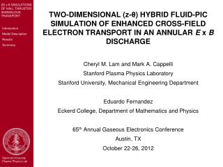
TWO-DIMENSIONAL (z- θ ) HYBRID FLUID-PIC SIMULATION OF ENHANCED CROSS-FIELD ELECTRON TRANSPORT IN AN ANNULAR E x B DISCHARGE. Cheryl M. Lam and Mark A. Cappelli Stanford Plasma Physics Laboratory Stanford University, Mechanical Engineering Department Eduardo Fernandez

E N D
TWO-DIMENSIONAL (z-θ) HYBRID FLUID-PIC SIMULATION OF ENHANCED CROSS-FIELD ELECTRON TRANSPORT IN AN ANNULAR E x B DISCHARGE Cheryl M. Lam and Mark A. Cappelli Stanford Plasma Physics Laboratory Stanford University, Mechanical Engineering Department Eduardo Fernandez Eckerd College, Department of Mathematics and Physics 65th Annual Gaseous Electronics Conference Austin, TX October 22-26, 2012
Hall Thruster • Electric (space) propulsion device • Demonstrated high thrust efficiencies • Up to 60% (depending on operating power) • Deployed production technology • Design Improvements • Better physics understanding • Basic Premise: Accelerate heavy (positive) ions through electric potential to create thrust • E x B azimuthal Hall current • Radial B field (r) • Axial E field (z) • Ionization zone (high electron density region) • Electrons “trapped” • Neutral propellant (e.g., Xe) ionized via collisions with electrons Plasma • Ions accelerated across imposed axial potential (Ez / Φz) & ejected from thruster
Anode Cathode Anode Exit Plane 2D (z-θ) Simulation Channel Diameter = 9 cm Channel Length = 8 cm • Hall thruster anomalous electron transport • Super-classical electron mobility observed in experiments1 • Correlated (azimuthal) fluctuations in ne ,ue • First fully-resolved 2D z-θ simulations of entire thruster • Predict azimuthal (E x B) flucutuations • Radial magnetic field (measured from SHT) • Imposed operating voltage Ez • Inform r-z model (Present r-z models used tuned mobility to account for azimuthal effects2,3) • Motivate 3D model (computationally expensive) • Hybrid Fluid-PIC • Ions: Non-magnetized, collisionless particles • Neutrals: Collisionless particles (Injected at anode; Local ionization rate) • Electrons: 2D Fluid • Continuity (Species & Current) • Momentum: Drift-Diffusion • Energy: 1D in z G 0 extends 4 cm past channel exit z: 40 points, non-uniform θ: 50 points, uniform ni = neQuasineutrality 1Meezan, N. B., Hargus, W.A., Jr., and Cappelli, M. A., Physical Review, Vol. 63, No. 2, 026410, 2001. 2Fife, J. M., Ph.D. Dissertation, Massachusetts Inst. of Technology, Cambridge, MA, 1999. 3Fernandez et al, “2D simulations of Hall thrusters,” CTR Annual Research Briefs, Stanford Univ.,1998.
Electron Fluid Equations Classical Mobility • Momentum: Drift-Diffusion • Neglect inertial terms • Correlated azimuthal fluctuations induce axial transport: Previous models under-predict Jez=qneuez θ fluctuations/dynamics
ξ t Azimuthal Fluctuations induce Axial Transport Eθ= E0cos(ωt) ne = n0cos(ωt + ξ) Consider Induced Current Induced current depends on phase shift ξ
where Electron Fluid Equations • Combine current continuity and electron momentum to get convection-diffusion equation for Φ: • Energy (Temperature) Equation • 1D in z (φ is electric potential)
LEAP FROG Time Advance Particle Positions & Velocities Neutrals & Ions (subject to F=qE) EGRID EPART Ionize Neutrals Inject Neutrals Calculate Plasma Properties ni-PART, vi-PART, nn-PART, vn-PART ni-GRID, vi-GRID, nn-GRID, vn-GRID QUASINEUTRALITY: ne = ni = nplamsa Spline RK4 Time Advance Te=Te(ne, ve) DIRECT SOLVE 2nd-order F-D Iterative Solve Φ Calculate Φ=Φ(ne, vi-GRID) ↔ EGRID Calculate ve=ve(Φ, ne, Te) r < ε0 CONVERGED r = Φ – Φlast-iteration Calculate vi-GRID-TEST= vi-GRID(EGRID) Solution Algorithm Boundary Conditions: • Dirichlet in z (Φ) • Periodic in θ
Plasma Density Electron Temperature Axial Ion Velocity Potential Time-Averaged Plasma Properties
E x B Plasma Density • Breathing Mode • ~10 KHz • Experiment: 20 KHz
E x B Axial Electron Velocity Distinct wave behavior observed: • Throughout channel (upstream) • Tilted: - z, + E x B • Lower frequency, slow moving, longer wavelength • Near exit plane • Peak Br, High shear (∂ueθ/∂z) • Tilted: + z, - ExB • Higher frequency, faster moving, shorter wavelength • Outside exit plane (downstream) • Purely axial: + z • Same structure (in θ) as exit plane waves
Electron Transport • Simulation predicts super-classical electron mobility Axial Electron Mobility:
Summary • Use z-θ simulation to understand impact of θ wave fluctuations on (axial) electron transport • Qualitative • Quantify impact: anomalous transport • Simulation predicts lower-frequency waves observed in experiment • Stable simulations at specific operating conditions • Initial Conditions • Transients Quasi-Steady State
Erosion rate on the inner wall Erosion rate on the outer wall Motivation • Primary Design Concern: Thruster Lifetime • Wall (ceramic insulator) erosion • Typical Lifetime: ~1000 hours (mpropellant≈ msystem) • Predictive Modeling & Simulation for Design Optimization Design Objective: Keep (fast) ions from hitting walls • Thruster geometry & operating voltage: fixed • Design parameter: B field (shape & strength) • Imposed B-field ↔ Ez • Underlying plasma physics • Electron transport • Plasma density & E field fluctuations • Ionization (via collisions) • Plasma-surface interactions (e.g., sputtering, electron damping, recombination at walls) • Certain physical phenomena observed in experiment not well understood Numerical experiments • Research focus: Azimuthal (θ) dynamics Axial (z) electron transport ** Movie courtesy of E. Sommier
Motivation • Hall thruster anomalous electron transport • Super-classical electron mobility observed in experiments1 • Correlated (azimuthal) fluctuations in ne and ue • 2D r-z models use tuned mobility to account for azimuthal effects2,3 • 3D model is computationally expensive • First fully-resolved 2D z-θ simulations of entire thruster ** Initial development by E. Fernandez • Predict azimuthal (ExB) fluctuations • Inform r-z model • Motivate 3D model Channel Diameter = 9 cm Channel Length = 8 cm 1Meezan, N. B., Hargus, W.A., Jr., and Cappelli, M. A., Physical Review, Vol. 63, No. 2, 026410, 2001. 2Fife, J. M., Ph.D. Dissertation, Massachusetts Inst. of Technology, Cambridge, MA, 1999. 3Fernandez et al, “2D simulations of Hall thrusters,” CTR Annual Research Briefs, Stanford Univ.,1998.
Hybrid Fluid-PIC Model • Ions: Collisionless particles (Particle-In-Cell approach) • Non-magnetized • Wall collisions not modeled • Neutrals: Collisionless particles (Particle-In-Cell approach) • Injected at anode per mass flow rate • Half-Maxwellian velocity distribution based on r-z simulation (w/ wall effects) • Ionized per local ionization rate • Based on fits to experimentally-measured collision cross-sections, assuming Maxwellian distribution for electrons • Electrons: Fluid • Continuity (species & current) • Momentum • Drift-diffusion equation • Inertial terms neglected • Energy (1D in z) • Convective & diffusive fluxes • Joule heating, Ionization losses, Effective wall loss Quasineutrality: ni = ne
Channel Diameter = 9 cm Channel Length = 8 cm Anode Cathode Anode Exit Plane extends 4 cm past channel exit z: 40 points, non-uniform θ: 50 points, uniform Geometry • 2D in z-θ • No radial dynamics • E x B + θ • Br: purely radial (measured from SHT) • Imposed operating (based on operating condition) G
Interpolation: Particle Grid rNW rNE FNW FNE rSE FSE rSW FSW Interpolation: Grid Particle PIC Ions & Neutrals • Particle-In-Cell (PIC) Approach • Particles: arbitrary positions • Force Particle acceleration Interpolate: Grid Particle • Plasma properties evaluated at grid points (Coupled to electron fluid solution) • Interpolate: Particle Grid • Bilinear Interpolation • Ions subject to electric force: ≈ 0 neglect
Electron Fluid Equations • Species Continuity • Current Continuity 0 ni = ne
Electron Fluid Equations • Momentum: Drift-Diffusion • Neglect inertial terms Previous models under-predict Jez=qneuez θ fluctuations/dynamics Classical Mobility
Electron Fluid Equations • Momentum: Drift-Diffusion • Neglect inertial terms • Correlated azimuthal fluctuations induce axial transport: Previous models under-predict Jez=qneuez θ fluctuations/dynamics
Unlike fully PIC codes, the electric potential is not obtained from a Poisson equation:
E x B Anode Cathode E x B E x B Fluctuations in θ f = 40 KHz λθ = 5 cm vph = 4000 m/s f = 700 KHz λθ = 4 cm vph = 40,000 m/s
Streak Plots E x B E x B
Future Work • Numerical Stability • Alternative solution algorithms • Timestep and grid refinement • Governing physics • Enhanced electron mobility • Wall model • Potential BC • Power supply circuit model • Recombination • Magnetized ions • Model validation against experiments