Download
1 / 19
210 likes | 423 Views
BASICS OF Piping. Ivy Tech Community College. Definitions – Page 703. DEFINITIONS The term piping can refer to any kind of pipe used in a wide range of applications. The word plumbing refers to the small diameter pipes within residences that carry water, gas, and waste.

E N D
BASICS OFPiping Ivy Tech Community College
Definitions – Page 703 • DEFINITIONS The term piping can refer to any kind of pipe used in a wide range of applications. The word plumbing refers to the small diameter pipes within residences that carry water, gas, and waste.
Definitions – Page 703 • DEFINITIONS Large underground pipes that transport waste water that is taken to treatment is known as civil piping. Piping used to transport fluids between storage tanks and processing equipment is called process piping.
Definitions – Page 704 • A flow diagram is a non-scale schematic that illustrates the layout and composition of a system using symbols. • A pipe drawing is the most complex drawing since it is to scale and provides plan, elevation and section views.
Definitions – Page 707 • A piping isometric is a pictorial drawing that illustrates a pipe run in three-dimensional form. See figure 22.10 on page 707. Assignment #10 is a piping isometric pictorial drawings. Information from this drawing is obtained from the piping drawings. Some pipe drawings are done in isometric form because lines can be measured and fits checked. Isometrics are extensively used in chemical process industries.
Definitions – Page 704 & 707 • Subassemblies of pie and fittings are constructed by pipe fitters and welders who use the piping spool drawing. This drawing is usually drawn orthographically and shows all of the pipe and fittings needed to assemble a segment of piping. Spools often are non-scale drawings that show all dimensions needed for assembly. A typical spool drawing is shown in figure on page 707.
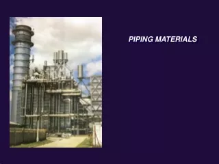
Types of Pipe – Page 709 • Steel Pipe: Carbon steel pipe is the preferred above ground pipe used in industry today. It is strong, relatively durable and can be welded and machined. • Copper pipe: and copper alloys are corrosion resistant and have excellent heat transfer properties. Often used in residential water lines, however, plastic pipe is becoming more prevalent in residential water lines.
Types of Pipe – Page 709 • Plastic Pipe: PVC (Polyvinyl Chloride) pipe is used for acids, salt solutions, alcohols, crude oil and other corrosive chemicals. PE (Polyethylene) is used for higher temperatures (up to 105 degrees F) and is suitable for water lines, sprinkler systems etc.
Types of Pipe – Page 709 • Clay pipe – is formed under high pressure from fire clays, shales, or a combination of the two. It is dried then fired at 2100 degrees F. Clay pipe is one of the most corrosion proof pipes available and is used in sanitary and industrial sewers.
Pipe connection methods – Page 710 • Butt Welding: is the most common method of joining pipes. Butt welded pipes provide a uniform wall thickness. Figure 22.16 shows a cross section of a butt weld. Pipe and fittings joined by butt welding are prepared with a beveled end to provide space for the welding operation.
Pipe connection methods – Page 710-712. • Other pipe connection methods include: socket welded, screwed, flanged, soldered, bell and spigot, mechanical joint, solvent welding connection, and flaring connection
Types of valves - Page 718 • Valves regulate fluids flow. Different valve types provide: on/off service, regulate flow of fluid, provide constant pressure, prevent dangerous pressure buildup and prevent backflow in the pipe. • The gate valve is used to to provide on/off service in a pipe. Refer to figure 22.31.
Types of valves - Page 719 • The most common type of regulating valve is the globe valve. Fluid flowing through the glove valve travels in a “S” pattern which allows the valve to maintain a close control on the flow. Refer to picture 22.34.
Types of valves - Page 721 • The most common type backflow valve is a check valve. Check valves prevent backflow by closing when the fluid stops flowing. • Safety valves such as a pop safety valve pop wide open when the pressure or piece of equipment reaches a set pressure. These valve are used for steam, air and gas lines only not for liquids. The relief valve provides the same function but is for liquids.
AutoCAD ISOMETRIC DRAWING – 2009 page 676 • Isometric drawings are more realistic than oblique drawings. The entire object appears as if it is tilted toward the viewer. The word isometric means “equal measure.” This equal measure refers to the angle between the three axes (120 deg) after the object has been tilted. The tilt angle is 30 degrees from horizontal. • All three axis lines can be measured using the same scale.
Double Line Drawing Pg 723 • The double line method is the easiest to interpret, because it looks like the actual pipe. This method is used to illustrate standard installation and in presentation drawings that are rarely revised. • Assignment is Figure 22.50 on page 731.
ISOMETRIC– 2009 page 678 • Circles appear as ellipses in an isometric drawing. • A basic rule to remember about isometric drawing is that lines that are parallel in and orthogonal view must be parallel in the isometric view. The ISOPLANE tool makes the task of positioning ellipses easy as well as toggling cross hair positions.
Settings for Isometric Drawing 2009 AutoCAD page 678. • You can set your isometric variables in the snap and grid table of the draft settings dialog box. Pick ISOMETRIC SNAP. Be sure to check the SNAP ON (F9) and the GRID ON (F7) check boxes if you want SNAP and GRID modes to be activated. Notice the crosshairs appear angled.
Settings for Isometric Drawing 2009 AutoCAD • Other tools that will be helpful are the: • ELLIPSE tool to place Isocircle’s when you are in Isometric Snap Mode. • Oblique dimensioning: Use the DIMALIGNED and DIMLINEAR tools.