Download
1 / 91
1.22k likes | 2.19k Views
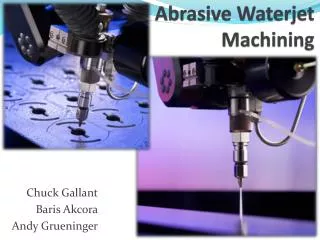
Electric Discharge Machining (EDM). Introduction. Sometimes it is referred to as spark machining , spark eroding , burning , die sinking or wire erosion Its a manufacturing process whereby a desired shape is obtained using electrical discharges (sparks).

E N D
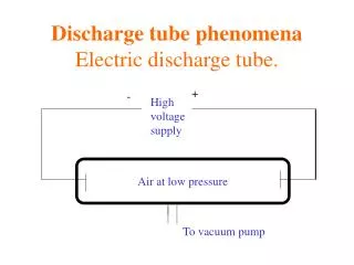
Introduction • Sometimes it is referred to as spark machining, spark eroding, burning, die sinking or wire erosion • Its a manufacturing process whereby a desired shape is obtained using electrical discharges (sparks). • Material is removed from the workpiece by a series of rapidly recurring current discharges between two electrodes, separated by a dielectric liquid and subject to an electric voltage. • One of the electrodes – ‘tool-electrode’ or ‘tool’ or ‘electrode’. • Other electrode - workpiece-electrode or ‘workpiece’. • As distance between the two electrodes is reduced, the current intensity becomes greater than the strength of the dielectric (at least in some points) causing it to break. 2
This allows current to flow between the two electrodes. • This phenomenon is the same as the breakdown of a capacitor. • As a result, material is removed from both the electrodes. • Once the current flow stops, new liquid dielectric is usually conveyed into the electrode zone enabling the solid particles (debris) to be carried away. • Adding new liquid dielectric in the electrode volume is commonly referred to as flushing. • Also, after a current flow, a difference of potential between the two electrodes is restored to what it was before the breakdown, so that a new liquid dielectric breakdown can occur. 3
History • In 1770, English Physicist Joseph Priestley studied the erosive effect of electrical discharges. • Furthering Priestley's research, the EDM process was invented by two Russian scientists, Dr. B.R. Lazarenko and Dr. N.I. Lazarenko in 1943. • In their efforts to exploit the destructive effects of an electrical discharge, they developed a controlled process for machining of metals. • Their initial process used a spark machining process, named after the succession of sparks (electrical discharges) that took place between two electrical conductors immersed in a dielectric fluid. • The discharge generator effect used by this machine, known as the Lazarenko Circuit, was used for many years in the construction of generators for electrical discharge. 4
History • New researchers entered the field and contributed many fundamental characteristics of the machining method we know today. • In 1952, the manufacturer Charmilles created the first machine using the spark machining process and was presented for the first time at the European Machine Tool Exhibition in 1955. • In 1969, Agie launched the world's first numerically controlled wire-cut EDM machine. • Seibu developed the first CNC wire EDM machine in 1972 and the first system was manufactured in Japan. • Recently, the machining speed has gone up by 20 times. • This has decreased machining costs by at least 30 percent and improved the surface finish by a factor of 1.5 5
General Aspects of EDM • EDM is a machining method primarily used for hard metals or those that would be very difficult to machine with traditional techniques. • EDM typically works with materials that are electrically conductive, although methods for machining insulating ceramics with EDM have been proposed. • EDM can cut intricate contours or cavities in hardened steel without the need for heat treatment to soften and re-harden them. • This method can be used with any other metal or metal alloy such as titanium, hastelloy, kovar, and inconel. • Also, applications of this process to shape polycrystalline diamond tools have been reported. 6
EDM – SystemControlled spark removes metal during electrical discharge machining
EDM – Types – Sinker EDM • Sinker EDM, also called cavity type EDM or volume EDM. • Consists of an electrode and workpiece submerged in an insulating liquid such as oil or other dielectric fluids. • The electrode and workpiece are connected to a suitable power supply. • The power supply generates an electrical potential between the two parts. • As the electrode approaches the workpiece, dielectric breakdown occurs in the fluid, forming a plasma channel, and a small spark jumps. • These sparks happen in huge numbers at seemingly random locations. • As the base metal is eroded, and the spark gap subsequently increased, the electrode is lowered automatically so that the process can continue. • Several hundred thousand sparks occur per second, with the actual duty cycle carefully controlled by the setup parameters. • These controlling cycles are sometimes known as "on time" and "off time“. 8
EDM – Types – Sinker EDM • The on time setting determines the length or duration of the spark. • Hence, a longer on time produces a deeper cavity for that spark and all subsequent sparks for that cycle. • This creates rougher finish on the workpiece. • The reverse is true for a shorter on time. • Off time is the period of time that one spark is replaced by another. • A longer off time, for example, allows the flushing of dielectric fluid through a nozzle to clean out the eroded debris, thereby avoiding a short circuit. • These settings can be maintained in micro seconds. • The typical part geometry is a complex 3D shape, often with small or odd shaped angles. 9
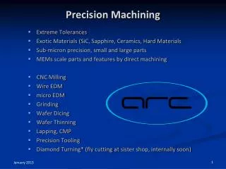
Wire-Cut EDM Machine • Uses thin brass or copper wire as electrode • Makes possible cutting most shapes and contours from flat plate materials • Complex shapes: tapers, involutes, parabolas, and ellipses • Process commonly used for: • Machining tungsten carbide, polycrystalline diamond, polycrystalline cubic boron nitride, pure molybdenum, difficult-to-machine material
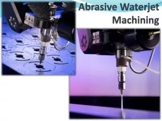
EDM – Types – Wire EDM (WEDM) • Also known as wire-cut EDM and wire cutting. • A thin single-strand metal wire (usually brass) is fed through the workpiece submerged in a tank of dielectric fluid (typically deionized water). • Used to cut plates as thick as 300 mm and to make punches, tools, and dies from hard metals that are difficult to machine with other methods. • Uses water as its dielectric fluid; its resistivity and other electrical properties are controlled with filters and de-ionizer units. • The water flushes the cut debris away from the cutting zone. • Flushing is an important factor in determining the maximum feed rate for a given material thickness. • Commonly used when low residual stresses are desired, because it does not require high cutting forces for material removal. 11
EDM - Components • The main components in EDM: • Electric power supply • Dielectric medium • Work piece & tool • Servo control unit. • The work piece and tool are electrically connected to a DC power supply. • The current density in the discharge of the channel is of the order of 10000 A/cm2 and power density is nearly 500 MW/cm2. • A gap, known as SPARK GAP in the range, from 0.005 mm to 0.05 mm is maintained between the work piece and the tool. • Dielectric slurry is forced through this gap at a pressure of 2 kgf/cm2 or lesser. 13
EDM – Working Principle • It is a process of metal removal based on the principle of material removal by an interrupted electric spark discharge between the electrode tool and the work piece. • In EDM, a potential difference is applied between the tool and workpiece. • Essential - Both tool and work material are to be conductors. • The tool and work material are immersed in a dielectric medium. • Generally kerosene or deionised water is used as the dielectric medium. • A gap is maintained between the tool and the workpiece. • Depending upon the applied potential difference (50 to 450 V) and the gap between the tool and workpiece, an electric field would be established. • Generally the tool is connected to the negative terminal (cathode)of the generator and the workpiece is connected to positive terminal (anode). 14
EDM – Working Principle • As the electric field is established between the tool and the job, the free electrons on the tool are subjected to electrostatic forces. • If the bonding energy of the electrons is less, electrons would be emitted from the tool. • Such emission of electrons are called or termed as ‘cold emission’. • The “cold emitted” electrons are then accelerated towards the job through the dielectric medium. • As they gain velocity and energy, and start moving towards the job, there would be collisions between the electrons and dielectric molecules. • Such collision may result in ionization of the dielectric molecule. • Ionization depends on the ionization energy of the dielectric molecule and the energy of the electron. 15
EDM – Working Principle • As the electrons get accelerated, more positive ions and electrons would get generated due to collisions. • This cyclic process would increase the concentration of electrons and ions in the dielectric medium between the tool and the job at the spark gap. • The concentration would be so high that the matter existing in that channel could be characterised as “plasma”. • The electrical resistance of such plasma channel would be very less. • Thus all of a sudden, a large number of electrons will flow from tool to job and ions from job to tool. • This is called avalanche motion of electrons. • Such movement of electrons and ions can be visually seen as a spark. • Thus the electrical energy is dissipated as the thermal energy of the spark. 16
EDM – Working Principle • The high speed electrons then impinge on the job and ions on the tool. • The kinetic energy of the electrons and ions on impact with the surface of the job and tool respectively would be converted into thermal energy or heat flux. • Such intense localized heat flux leads to extreme instantaneous confined rise in temperature which would be in excess of 10,000oC. • Such localized extreme rise in temperature leads to material removal. • Material removal occurs due to instant vaporization of the material as well as due to melting. • The molten metal is not removed completely but only partially.
EDM – Working Principle • Upon withdrawal of potential difference, plasma channel collapses. • This ultimately creates compression shock waves on both the electrode surface. • Particularly at high spots on work piece surface, which are closest to the tool. • This evacuates molten material and forms a crater around the site of the spark. • The whole sequence of operation occurs within a few microseconds. 18
Servo EDM – Schematic Tool Rectifier Work 220-V AC Current Control
EDM – Working Principle • Thus to summarise, the material removal in EDM mainly occurs due to formation of shock waves as the plasma channel collapse owing to discontinuation of applied potential difference • Generally the workpiece is made positive and the tool negative. • Hence, the electrons strike the job leading to crater formation due to high temperature and melting and material removal. • Similarly, the positive ions impinge on the tool leading to tool wear. • In EDM, the generator is used to apply voltage pulses between the tool and job. • A constant voltage is not applied. Only sparking is desired rather than arcing. • Arcing leads to localized material removal at a particular point whereas sparks get distributed all over the tool surface leading to uniform material removal. 21
EDM – Power & Control Circuits • Two broad categories of generators (power supplies) are in use on EDM. • Commercially available: RC circuits based and transistor controlled pulses. • In the first category, the main parameters to choose from at setup time are the resistance(s) of the resistor(s) and the capacitance(s) of the capacitor(s). • In an ideal condition, these quantities would affect the maximum current delivered in a discharge. • Current delivery in a discharge is associated with the charge accumulated on the capacitors at a certain moment. • Little control is expected over the time of discharge, which is likely to depend on the actual spark-gap conditions. • Advantage: RC circuit generator can allow the use of short discharge time more easily than the pulse-controlled generator. 25
EDM – Power & Control Circuits • Also, the open circuit voltage (i.e. voltage between electrodes when dielectric is not broken) can be identified as steady state voltage of the RC circuit. • In generators based on transistor control, the user is usually able to deliver a train of voltage pulses to the electrodes. • Each pulse can be controlled in shape, for instance, quasi-rectangular. • In particular, the time between two consecutive pulses and the duration of each pulse can be set. • The amplitude of each pulse constitutes the open circuit voltage. • Thus, maximum duration of discharge is equal to duration of a voltage pulse. • Maximum current during a discharge that the generator delivers can also be controlled. 26
EDM – Power & Control Circuits • Details of generators and control systems on EDMs are not always easily available to their user. • This is a barrier to describing the technological parameters of EDM process. • Moreover, the parameters affecting the phenomena occurring between tool and electrode are also related to the motion controller of the electrodes. • A framework to define and measure the electrical parameters during an EDM operation directly on inter-electrode volume with an oscilloscope external to the machine has been recently proposed by Ferri et al. • This would enable the user to estimate directly the electrical parameter that affect their operations without relying upon machine manufacturer's claims. • When machining different materials in the same setup conditions, the actual electrical parameters are significantly different. 27
EDM – Power & Control Circuits • When using RC generators, the voltage pulses, shown in Fig. are responsible for material removal. • A series of voltage pulses (Fig.) of magnitude about 20 to 120 V and frequency on the order of 5 kHz is applied between the two electrodes. 28
EDM – Electrode Material • Electrode material should be such that it would not undergo much tool wear when it is impinged by positive ions. • Thus the localised temperature rise has to be less by properly choosing its properties or even when temperature increases, there would be less melting. • Further, the tool should be easily workable as intricate shaped geometric features are machined in EDM. • Thus the basic characteristics of electrode materials are: • High electrical conductivity – electrons are cold emitted more easily and there is less bulk electrical heating • High thermal conductivity – for the same heat load, the local temperature rise would be less due to faster heat conducted to the bulk of the tool and thus less tool wear. 31
EDM – Electrode Material • Higher density – for less tool wear and thus less dimensional loss or inaccuracy of tool • High melting point – high melting point leads to less tool wear due to less tool material melting for the same heat load • Easy manufacturability • Cost – cheap • The followings are the different electrode materials which are used commonly in the industry: • Graphite • Electrolytic oxygen free copper • Tellurium copper – 99% Cu + 0.5% tellurium • Brass 32
Electrode • Spool of brass, copper, tungsten, molybdenum, or zinc wire ranging from .002 to .012 in. in diameter (2 to 100 lb) • Continuously travels from supply spool to takeup spool so new wire always in spark area • Both electrode wear and material-removal rate from workpiece depend on: • Material's electrical and thermal conductivity, its melting point and duration and intensity of electrical pulses
Electrode (Tool) Wear • During discharge process, tool subject to wear or erosion • Difficult to hold close tolerances as tool gradually loses its shape during machining operation • Average wear ratio of workpiece to electrode is 3:1 for metallic tools • Graphite electrodes wear ratio 10:1
EDM Process • Servo mechanism • Automatically maintains constant gap ~.0005 to .001 in. between electrode and work • Advance tool into workpiece, senses and corrects any shorted condition by rapidly retracting tool (vertical movement) • Feed control applied to table for horizontal moves • EDM power supply • Provides direct current electrical energy for electrical discharges between tool and work
Servo Mechanism • Controls cutting current levels, feed rate of drive motors, and traveling speed of wire • Automatically maintains constant gap of .001 to .002 in. between wire and workpiece • Important there be no physical contact • Advances workpiece into wire, senses work-wire spacing, and slows or speeds up drive motors to maintain proper arc gap
EDM – Electrode Movement • In addition to the servo-controlled feed, the tool electrode may have an additional rotary or orbiting motion. • Electrode rotation helps to solve the flushing difficulty encountered when machining small holes with EDM. • In addition to the increase in cutting speed, the quality of the hole produced is superior to that obtained using a stationary electrode. • Electrode orbiting produces cavities having the shape of the electrode. • The size of the electrode and the radius of the orbit (2.54 mm maximum) determine the size of the cavities. • Electrode orbiting improves flushing by creating a pumping effect of the dielectric liquid through the gap. 37
EDM – Electrode Wear • The melting point is the most important factor in determining the tool wear. • Electrode wear ratios are expressed as end wear, side wear, corner wear, and volume wear. • “No wear EDM” - when the electrode-to-workpiece wear ratio is 1 % or less. • Electrode wear depends on a number of factors associated with the EDM, like voltage, current, electrode material, and polarity. • The change in shape of the tool electrode due to the electrode wear causes defects in the workpiece shape. • Electrode wear has even more pronounced effects when it comes to micromachining applications. • The corner wear ratio depends on the type of electrode. • The low melting point of aluminum is associated with the highest wear ratio. 39
EDM – Dielectric • In EDM, material removal mainly occurs due to thermal evaporation and melting. • As thermal processing is required to be carried out in absence of oxygen so that the process can be controlled and oxidation avoided. • Oxidation often leads to poor surface conductivity (electrical) of the workpiece hindering further machining. • Hence, dielectric fluid should provide an oxygen free machining environment. • Further it should have enough strong dielectric resistance so that it does not breakdown electrically too easily. • But at the same time, it should ionize when electrons collide with its molecule. • Moreover, during sparking it should be thermally resistant as well. • Generally kerosene and deionised water is used as dielectric fluid in EDM. 40
EDM – Dielectric • Tap water cannot be used as it ionises too early and thus breakdown due to presence of salts as impurities occur. • Dielectric medium is generally flushed around the spark zone. • It is also applied through the tool to achieve efficient removal of molten material. • Three important functions of a dielectric medium in EDM: • Insulates the gap between the tool and work, thus preventing a spark to form until the gap voltage are correct. • Cools the electrode, workpiece and solidifies the molten metal particles. • Flushes the metal particles out of the working gap to maintain ideal cutting conditions, increase metal removal rate. • It must be filtered and circulated at constant pressure. 41
EDM – Dielectric • The main requirements of the EDM dielectric fluids are adequate viscosity, high flash point, good oxidation stability, minimum odor, low cost, and good electrical discharge efficiency. • For most EDM operations kerosene is used with certain additives that prevent gas bubbles and de-odoring. • Silicon fluids and a mixture of these fluids with petroleum oils have given excellent results. • Other dielectric fluids with a varying degree of success include aqueous solutions of ethylene glycol, water in emulsions, and distilled water. 42
EDM – Flushing • One of the important factors in a successful EDM operation is the removal of debris (chips) from the working gap. • Flushing these particles out of the working gap is very important, to prevent them from forming bridges that cause short circuits. • EDMs have a built-in power adaptive control system that increases the pulse spacing as soon as this happens and reduces or shuts off the power supply. • Flushing – process of introducing clean filtered dielectric fluid into spark gap. • If flushing is applied incorrectly, it can result in erratic cutting and poor machining conditions. • Flushing of dielectric plays a major role in the maintenance of stable machining and the achievement of close tolerance and high surface quality. • Inadequate flushing can result in arcing, decreased electrode life, and increased production time. 43
EDM – Flushing • Four methods: 1. Normal flow 2. Reverse flow 3. Jet flushing 4. Immersion flushing 44
EDM – Flushing • Normal flow (Majority) • Dielectric is introduced, under pressure, through one or more passages in the tool and is forced to flow through the gap between tool and work. • Flushing holes are generally placed in areas where the cuts are deepest. • Normal flow is sometimes undesirable because it produces a tapered opening in the workpiece. • Reverse flow • Particularly useful in machining deep cavity dies, where the taper produced using the normal flow mode can be reduced. • The gap is submerged in filtered dielectric, and instead of pressure being applied at the source a vacuum is used. • With clean fluid flowing between the workpiece and the tool, there is no side sparking and, therefore, no taper is produced. 45
EDM – Flushing • Jet flushing • In many instances, the desired machining can be achieved by using a spray or jet of fluid directed against the machining gap. • Machining time is always longer with jet flushing than with the normal and reverse flow modes. • Immersion flushing • For many shallow cuts or perforations of thin sections, simple immersion of the discharge gap is sufficient. • Cooling and debris removal can be enhanced during immersion cutting by providing relative motion between the tool and workpiece. • Vibration or cycle interruption comprises periodic reciprocation of the tool relative to the workpiece to effect a pumping action of the dielectric. 46
EDM – Flushing • Synchronized, pulsed flushing is also available on some machines. • With this method, flushing occurs only during the non-machining time as the electrode is retracted slightly to enlarge the gap. • Increased electrode life has been reported with this system. • Innovative techniques such as ultrasonic vibrations coupled with mechanical pulse EDM, jet flushing with sweeping nozzles, and electrode pulsing are investigated by Masuzawa (1990). 47
EDM – Flushing • For proper flushing conditions, Metals Handbook (1989) recommends: • Flushing through the tool is more preferred than side flushing. • Many small flushing holes are better than a few large ones. • Steady dielectric flow on the entire workpiece-electrode interface is desirable. • Dead spots created by pressure flushing, from opposite sides of the workpiece, should be avoided. • A vent hole should be provided for any upwardly concave part of the tool-electrode to prevent accumulation of explosive gases. • A flush box is useful if there is a hole in the cavity. 48
Methods of Circulating Dielectrics • Must be circulated under constant pressure • Pressure used generally begins with 5 psi and increased until optimum cutting obtained • Four methods to circulate dielectric fluid • All must use fine filters in system to remove metal particles so they are not recirculated
Pressure Down Through the Electrode • Hole drilled through electrode and dielectric fluid forced through electrodeand between it and work • Rapidly flushes awaymetal particles