Download
1 / 38
380 likes | 499 Views
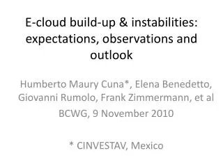
E Cloud Experiments and Instabilities: The C ESR TA Experience October 4, 2011. Mark Palmer for the C ESR TA Collaboration. Outline. Introduction R&D Program Scope and Plan Overview of Electron Cloud R&D Mitigation S tudies EC-Induced Instabilities

E N D
ECloud Experiments and Instabilities:The CESRTA ExperienceOctober 4, 2011 Mark Palmer for the CESRTA Collaboration
Outline • Introduction • R&D Program Scope and Plan • Overview of Electron Cloud R&D • Mitigation Studies • EC-Induced Instabilities • Recommendationsfor the ILC Positron DR • Future Plans Low Emittance Rings 2011 - Heraklion, Crete
Introduction • The CESRTA Electron Cloud R&D Program is one of four critical R&D programs identified for the ILC Technical Design Phase: “The work done during the RDR phase identified many high-risk challenges that required R&D. The four highest-priority critical risk-mitigating R&D areas were prioritised as: 1. SCRF cavities capable of reproducibly achieving at least 35 megavolts/metre(MV/m). 2. A cryomodule consisting of eight or more cavities, operating at a gradient of 31.5 MV/m. 3. Linac ‘string test’ (or integration test) of more than one cryomodulelinacwith beam. 4. Development of models and mitigation techniques for electron cloud effects in the positron damping ring.” • From March 2008 – March 2011, it was supported through a joint agreement between the U.S. DOE and NSF ISBN: 978-3-935702-56-0 2011 Low Emittance Rings 2011 - Heraklion, Crete
The CESRTA Collaboration • The program has involved senior researchers, post-docs and graduate students from a dozen laboratories and universities world-wide. • Over 100 contributors to the Phase I Report – presently in preparation Low Emittance Rings 2011 - Heraklion, Crete
R&D Goals • Studies of Electron Cloud Growth and Mitigation • Study EC growth and methods to mitigate it (particularly wigglers and dipoles) • Benchmark and expand existing simulation codes a validate projections to the ILC DR • Low Emittance Operations • EC beam dynamics studies at ultra low emittance(CESRTA vertical emittance target: ey<20 pm-rad) • Beam instrumentation for ultra low emittance beams • x-Ray Beam Size Monitor targeting bunch-by-bunch (single pass) readout • Beam Position Monitor upgrade • Develop LET tuning tools • Studies of EC Induced Instability Thresholds and Emittance Dilution • Measure instability thresholds and emittance growth at ultra low emittance • Validate EC simulations in the low emittance parameter regime • Confirm the projected impact of the EC on ILC DR performance • Inputs for the ILC DR Technical Design Low Emittance Rings 2011 - Heraklion, Crete
The CESRTA R&D Program – Phase I… March 1, 2008: Formal Start of Program Start of Phase II Funding Low Emittance Rings 2011 - Heraklion, Crete
The CESR Conversion • Damping Wiggler Straight for ultra low emittance operation • 4 EC experimental regions • Beam and EC instrumentation upgrades Q15W ExperimentalChamber Installed Diagnostic Wigglers Low Emittance Rings 2011 - Heraklion, Crete
CESR Conversion: Low e Instrumentation • x-Ray Beamsize Monitor-xBSM • Single pass measurement capability • Targeted at ~10 mm beams • BPM system upgrade • X-ray Optics • Pinhole • Fresnel Zone Plate • Coded Aperture Pinhole 0.8×10¹⁰ particles UHV InGaAsArray CA FZP Low Emittance Rings 2011 - Heraklion, Crete
CESR Conversion: CESRTA Parameters Lattice Parameters Ultra low emittance baseline lattice IBS Studies Range of optics implemented Beam dynamics studies Control g flux in EC experimental regions Low Emittance Rings 2011 - Heraklion, Crete
Will briefly touch on a few key highlights LET details in Jim Shanks talk yesterday Beam instrumentation details in Mike Billing’s talk tomorrow More complete treatment to appear in the CESRTA Phase I Report R&D ResultsOverview EC Mitigation StudiesBeam Dynamics Studies Low Emittance Rings 2011 - Heraklion, Crete
R&D Status Overview • CESR Configuration • Damping ring layout • 4 dedicated EC experimental regions • Upgraded vacuum/EC instrumentation • Energy flexibility from 1.8 to 5.3 GeV • Beam Instrumentation • xBSM for positrons and electrons • High resolution digital BPM system • Feedback system for 4ns bunch spacing • EC Diagnostics and Mitigation • ~30 RFAs presently deployed • TE wave measurement capability in each experimental region • Time-resolved shielded pickups in 3 experimental locations (2 with transverse information) • Over 20 individual mitigation studies conducted in Phase I • 20 chambers • 2 sets of in situ SEY measurements • Follow-on studies in preparation for Phase II extension of program • Low Emittance Tuning and Beam Dynamics Studies • Regularly achieving <10pm vertical emittance • Continuing to explore the emittance reach of new instrumentation and techniques for LET • Systematic studies of beam instability thresholds and emittance dilution • Detailed comparison with simulation ongoing • Additional tests envisioned based on initial observations Tune shifts for 4ns bunch spacing - feedback error signal D. Teytelman Low Emittance Rings 2011 - Heraklion, Crete
EC Mitigations ✗= deployed in CESR Arc, Jan 2011 = chamber(s) deployed = installed Jan 2011 Low Emittance Rings 2011 - Heraklion, Crete
Drift Region Observations • Q15 E/W Arc Studies a Coating Tests • Bare Al vsTiN, amorphous C, and diamond-like C (all on Al) • Vacuum performance (eg. dP/dI) poorer for coatings • EC performance of TiN and the carbon coatings in a similar range a consistent with in situ SEY measurements for processed TiN and aC near unity • Also NEG tests in L3 experimental region • Requires detailed simulation capability for direct comparison In Situ SEY Station Low Emittance Rings 2011 - Heraklion, Crete
Drift Region Data vs Simulation • Goal: Evaluate surfaces under a wide range of conditions to evaluate in situ surface parameters using the RFA data • Vary: Bunch charge & spacing, species, beam energy, RFA retarding voltage • Fit for: Peak value of the true SEYEnergy of the SEY peakElastic scattering fraction, d(0)Rediffused scattering fractionQuantum effeiciency • Incorporate constraints from other sources • Time-resolved detector data • 3D photon transport model (Synrad3D) 5.3GeV Dataa Low Emittance Rings 2011 - Heraklion, Crete
Time-Resolved (SPU) Comparisons: d(0) • spu e- signal from B1sensitive to PE model Bare Al TiN Low Emittance Rings 2011 - Heraklion, Crete
Quadrupole Observations • RFA currents higher than expected from “single turn” simulations • Turn-to-turn cloud buildup • ~20 turn effect • Issue also being studied in wigglers • Clear improvement with TiN 20 bunch train e+ 45 bunch train e+ Low Emittance Rings 2011 - Heraklion, Crete
Dipole Observations • Data shown: 5.3 GeV, 14ns • 810 Gauss dipole field • Signals summed over all collectors • Al signals ÷40 Longitudinally grooved surfaces offer significant promise for EC mitigation in the dipole regions of the damping rings 20 bunch train e+ 20 bunch train e- Low Emittance Rings 2011 - Heraklion, Crete
Wiggler Observations 0.002”radius Low Emittance Rings 2011 - Heraklion, Crete
EC Tune Shifts: Pinged Train + Witnesses Simulations with direct radiation rates, reflectivity=15%, QE=12%, Gaussian PE spectrum SEY=2 Simulations with Synrad3D distributions, QE=10.8% (9.7%) in dipoles(drifts), Lorentzian PE spectrum SEY=2 Low Emittance Rings 2011 - Heraklion, Crete
Photons and PEY • Better photon reflection and transport model needed for simulations and data analysis • Time-resolved measurements indicate that we also need to have a better PE spectrum (fitting of RFA data also requires this) • Synrad3D (Sagan, et al.) answers this need, but work remains • Fully validate real VC geometries • Diffuse scattering issues (see next slide) • Surface roughness issues Tune Shift Anal w/Witness Bunches Data Synrad2D Synrad3D 150m 100m 5.1 reflection typ. • Requirements for PE control in the ILC and CLIC DRs a High Priority Low Emittance Rings 2011 - Heraklion, Crete
Wiggler Ramp • Plots show TE Wave and RFA response as a function of wiggler field strength • Large increase in signal as soon as radiation fan begins to strike local VC surface a significant diffuse scattering component 1x45x0.75mA e+, 2.1 GeV, 14ns bunch spacing RFA Response TEW Response Low Emittance Rings 2011 - Heraklion, Crete
Beam Dynamics Studies • Have taken advantage of the ability to achieve repeatable operation with ey≤ 20pm in the 2 GeV low emittance lattice since spring 2010 • Studies to date have examined the dependence on: • Bunch spacing & intensity • Chromaticity • Feedback • Emittance • Beam energy • Species Low Emittance Rings 2011 - Heraklion, Crete
Systematic Studies of Instability Thresholds • Spectral methods offer powerful tool for self-consistent analysis for the onset of instabilities • Tune shifts along train a ring-wide integrated cloud density near beam • Onset of synchrobetatron sidebands a instability thresholds Data POSINST Simulation Strength of upper & lowersynchrobetatron sidebands (H,V) chrom = (1.33,1.155) Avg current/bunch 0.74 mA dBm Low Emittance Rings 2011 - Heraklion, Crete
EC Instability: Vertical Head-Tail Lines • Study vs Chromaticity • Particles/bunch = 1.2x10¹⁰ • Data sets • 142: (H,V) = Q’ (1.34, 1.99) • 129: (H,V) = Q’ (1.07, 1.78) • 147: (H,V) = Q’ (1.33, 1.16) m=+1 m=-1 Low Emittance Rings 2011 - Heraklion, Crete
EC Instability: Vertical Head-Tail Lines • Study vs Bunch Current Q’ (H,V) = (1.34, 1.99) 142: Nb = 1.2 x10¹⁰ 150: Nb = 1.5 x10¹⁰ m=+1 m=-1Q’ (H,V) = (1.33, 1.16) 178: Nb = 7.5 x10⁹ 147: Nb = 1.2 x10¹⁰ m=+1 m=-1 Low Emittance Rings 2011 - Heraklion, Crete
EC Instability: Vertical Head-Tail Lines • Study vs Vertical Emittance • Particles/bunch = 1.2 x10¹⁰ • Data sets • 147: ey ~ 20 pm • 158: ey ~ 300 pm m=+1 m=-1 Low Emittance Rings 2011 - Heraklion, Crete
EC Instability: Vertical Head-Tail Lines • Study vs Species • Particles/bunch = 1.2 x10¹⁰ • Data sets • 154: Electrons • 166: Positrons m=+1 m=-1 Low Emittance Rings 2011 - Heraklion, Crete
Simulation Program • CMAD simulationsare being validatedagainst CESRTA measurements and applied to analysis of the ILC DR Low Emittance Rings 2011 - Heraklion, Crete
PEHTS Simulations (KEK) • Simulations for 2 GeV CESRTA show beam size growth, and head-tail line emergence, at a cloud density close to what is measured. • 5 GeV simulations show splitting of dipole line, also seen in the data. • Simulations show very little incoherent emittance growth below threshold for CESRTA. • These simulations predict a threshold of about 2x10¹¹/m3 for a 6.4 km ILCDR with a =4x10⁻⁴ From Jin et al, “Electron Cloud Effects in Cornell Electron Storage Ring Test Accelerator and International Linear Collider Damping Ring”, JJAP50 (2011) 026401 Low Emittance Rings 2011 - Heraklion, Crete
Beam Size • Measure Bunch-by-Bunch Beam Size • Beam size enhanced at head and tail of trainSource of blow-up at head appears to be due to a long lifetime component of the cloudBunch lifetime of smallest bunches consistent with observed single bunch lifetimes during LET (Touschek-limited) consistent with relative bunch sizes. • Beam size measured around bunch 5 is consistent with ey~ 20pm-rad [sy=11.00.2 mm, bsource=5.8m] 0.8×10¹⁰ e+/bunch, Each point: Average of 4K single-turn fits Consistentwith onsetof instability Single Turn FitBunch 5 2×10¹⁰ e+/bunch Sub-threshold emittance growth? Consistentwith 20 pm-rad Evidence for Long-termCloud Low Emittance Rings 2011 - Heraklion, Crete
2.0 x10¹⁰ /bunch, 14 ns spacing 4096 turns Bunch 5 Sidebands appear at ~size blow-up threshold Single-bunch, single-turn fits averaged over turns Bunch 25 V. tune Bunch-by-bunch position spectra Displacement Size Bunch 45 Low Emittance Rings 2011 - Heraklion, Crete
Implications for the ILC DR • Overall we see reasonable agreement between data and simulation for the onset of the instabilities • Provides confidence in our evaluations of head-tail instability thresholds • Work is still ongoing to understand the impact of sub-threshold emittance growth • Trapped EC in the quadrupoles and wigglers has taken on greater significance given recent obesrvations • Simulation and experimental effortswill continue in thisarea • No precursor bunch • With precursor bunch 2 GeV, 30 bunch train, 0.75 mA/bunch (1.2×10¹⁰) Low Emittance Rings 2011 - Heraklion, Crete
Newer Initiative: Drive-Damp Observations Method Observe signal from single BPM button, connecting to spectrum analyzer. Gate off feedback for the bunch being observed. Excite the beam for 1 msec burst at frequency for mode of oscillation via Stripline Feedback Kicker. To observe Head-tail modes, excite the bunch at Synchrotron Tune, producing large longitudinal motion. Dipole (m=0) Mode Head-Tail (m=-1) Mode Low Emittance Rings 2011 - Heraklion, Crete
Summary of Observations • Tune shift measurements & simulations provide good estimates for the cloud densities along train • Single-bunch frequency spectra in multi-bunch positron trains • Exhibit m=+/- 1 head-tail (HT) lines • Separation from m=0 vertical line by about synchrotron frequency • Occurs for some of the bunches during the train • Beam size blowup is observed for roughly same bunches as HT lines. • Onset of HT lines depends strongly on • Vertical chromaticity • Beam current • Number of bunches • Onset of HT lines has weak dependence on • Synchrotron tune • Vertical beam size • Vertical feedback. (Important for benchmarking simulations-> ILC DR extrapolations.) Low Emittance Rings 2011 - Heraklion, Crete
Inputs for the ILC Technical Design • ECLOUD `10 – October 8-12, 2010, Cornell University • Presentation of all key CESRTA results allowed review and feedback from the EC community • Satellite Meeting of the ILC DR EC Working Group on October 13, 2010 • Baseline EC mitigation plan for the ILCDR using CESRTA results along with results obtained from our collaborating laboratories (particularly CERN, INFN-LNF, KEK, SLAC) • Evaluations of the beam dynamics studies suggest that our projections of head-tail instability thresholds for the ILC DR are reasonable • One area of particular concern identified: Sub-threshold emittance growth a more margin may be required • 3.2 km ILC Damping Ring Design • Phase I results on EC mitigations are consistent with the low power option (1300 bunches) achieving its design goals! • Sufficient margin exists such that this design appears viable even in the event that the allowed EC density in the ring is lowered due to concerns about sub-threshold emittance growth. Further effort to make this statement more quantitative is highly desirable! • Concerns remain about moving to the high power option (2600 bunches) with a single positron ring (baseline plan is to add another e+ ring). Further effort to determine whether we can avoid this option is desirable! Low Emittance Rings 2011 - Heraklion, Crete
EC Working Group Mitigation Plan Mitigation Evaluation conducted at satellite meeting of ECLOUD`10(October 13, 2010, Cornell University) *Drift and Quadrupole chambers in arc and wiggler regions will incorporate antechambers • Preliminary CESRTA results and simulations suggest the presence of sub-threshold emittance growth • Further investigation required • May require reduction in acceptable cloud density a reduction in safety margin • An aggressive mitigation plan is required to obtain optimum performance from the 3.2km positron damping ring and to pursue the high current option S. Guiducci, M. Palmer, M. Pivi, J. Urakawa on behalf of the ILC DR Electron Cloud Working Group Low Emittance Rings 2011 - Heraklion, Crete
Comparison of 6.4 and 3.2 km DR Options • Summer 2010 Evaluation • Comparison of Single Bunch EC Instability Thresholds for: • 6.4km ring with 2600 bunches • 3.2km ring with 1300 bunches • same average current • Both ring configurations exhibit similar performance • a 3.2km ring (low current option) is an acceptable baseline design choice SEY 1.4 SEY 1.2 antechamber antechamber antechamber antechamber S. Guiducci, M. Palmer, M. Pivi, J. Urakawa on behalf of the ILC DR Electron Cloud Working Group Low Emittance Rings 2011 - Heraklion, Crete
The Future • CESRTA • Phase II program is now funded (3 years) • Continue to compare simulation and data in a low emittance regime which approaches the ILC DR specification • Validate EC simulations against data (including critical extensions to models) • Time-resolved studies in dipoles and quadrupoles • Continued evaluation of the durability of coatings • Extended program allows for new studies • IBS studies and detailed comparison with simulation are of particular importance for the CLIC DR design • Tools and diagnostics are applicable to Fast Ion Instability studies • Continue the development of instrumentation and techniques useful for low emittance rings Continued refinement basedon Phase I results Low Emittance Rings 2011 - Heraklion, Crete