Download

1 / 41
460 likes | 673 Views
Energy Conversion. Specific energy. The specific energy of a hydro power plant is the quantity of potential and kinetic energy which 1 kilogram of the water delivers when passing through the plant from an upper to a lower reservoir.

E N D
Specific energy The specific energy of a hydro power plant is the quantity of potential and kinetic energy which 1 kilogram of the water delivers when passing through the plant from an upper to a lower reservoir. The expression of the specific energy is Nm/kg or J/kg and is designated as m2/s2.
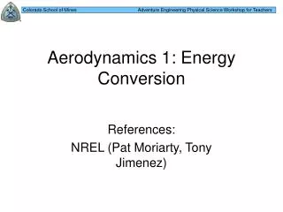
Gross Head Hgr zres ztw Reference line
Gross Specific Hydraulic Energy In a hydro power plant, the difference between the level of the upper reservoir zres and the level of the tail water ztw is defined as the gross head: Hgr = zres - ztw [m] The corresponding gross specific hydraulic energy:
Gross Power where: Pgr is the gross power of the plant [W] is the density of the water [kg/m3] Q is the discharge [m3/s]
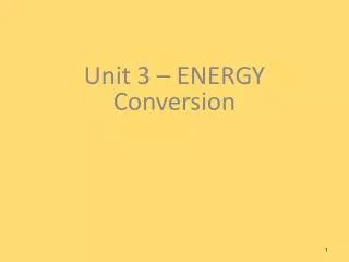
Net Head h1 abs c1 ztw z1 Reference line
Impulse turbines(Partial turbines) The hydraulic energy of the impulse turbines are completely converted to kinetic energy before transformation in the runner
Impulse turbines(Partial turbines) Pelton Turgo
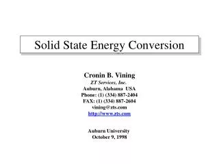
Reaction turbines(Full turbines) In the reaction turbines two effects cause the energy transfer from the flow to mechanical energy on the turbine shaft. Firstly it follows from a drop in pressure from inlet to outlet of the runner. This is denoted thereaction partof the energy conversion. Secondly changes in the directions of the velocity vectors of the flow through the canals between the runner blades transfer impulse forces. This is denoted the impulse part of the energy conversion.
Reaction turbines(Full turbines) Francis Kaplan Bulb
y c2y c2x c1y dl c1x x Reaction forces in a curved channel Newton’s 2.law in the x-direction: where: A is the area [m2] c is the velocity [m/s] is the density of the water [kg/m3] Q is the discharge [m3/s]
Reaction forces in a curved channel y Newton’s 2.law in the x-direction: c2y Rx Fx c2x c1y dl c1x x Fx is the force that acts on the fluid particle from the wall. Rx is the reaction force that acts on the wall from the fluid: Rx = -Fx
y Ry c2y R Rx c2x c1y dl c1x x Reaction forces in a curved channel Integrate the forces in the x-direction: Integrate the forces in the y-direction: Using vectors give:
Reaction forces in a curved channelForce-Momentum Equation R1 y c2 R R2 c1 x
Let the channel rotate around the point ”o”. What is the torque ? Let us define the u-direction as the normal of the radius (or tangent to the circle) Torque = force · arm: r1 c1 cu1 cu2 c2 r2 a1 w o a2
r1 c1 cu1 cu2 c2 r2 a1 o a2 Euler’s turbine equation Power : P = T•w [W] Angular velocity: w[rad/s] Peripheral velocity: u = w•r [m/s]
Euler’s turbine equation Output power from the runner Available hydraulic power
Velocity triangle cu v cm c
Francis turbine cu1 u1 b1 cm1 v1 c1 u2 b2 c2 D1 D2 v2
v1 c1 u1 v2 c2 u2 w
v1 c1 u1 w v2 c2 u2 w
Velocity triangles for an axial turbine Guidevanes Runnerblades
u2 c2 v2 v1 c1 u1 c w
Inlet and outlet velocity diagram for reaction turbines Guidevanes u1 a1 b1 c1 v1 u2 Runner vanes b2 c2 v2
V1=C1- U V2
Example1Francis turbine D1 D2 B1
Example1Francis turbine Head: 150 m Q: 2 m3/s Speed: 1000 rpm D1: 0,7 m D2: 0,3 m B1: 0,1 m h: 0,96 Find all the information to draw inlet and outlet velocity triangles D1 D2 B1
Example1Inlet velocity triangle u1 D1 v1 c1
Example1Inlet velocity triangle cu1 u1 b1 cm1 D1 w1 c1 B1
Example1Inlet velocity triangle cu1 u1 We assume cu2 = 0 b1 cm1 w1 c1
Example1Inlet velocity triangle cu1 u1 u1 = 36,7 m/s cu1 = 33,4 m/s cm1 = 9,1 m/s b1 cm1 w1 c1
Example1Outlet velocity triangle u2 We assume: cu2 = 0 and we choose: cm2 = 1,1· cm1 b2 c2 v2
Exercise1Francis turbine Head: 543 m Q: 71,5 m3/s Speed: 333 rpm D1: 4,3 m D2: 2,35 m B1: 0,35 m h: 0,96 cm2 : 1,1· cm1 Find all the information to draw inlet and outlet velocity triangles D1 D2 B1
Exercise 2Francis turbine Speed: 666 rpm D1: 1,0 m h: 0,96 c1: 40 m/s a1: 40o Find: H b1