Download

1 / 26
260 likes | 368 Views
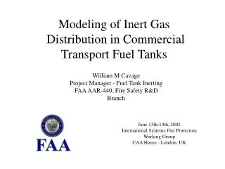
FAA Inerting System Flight Testing on an Airbus A320. William Cavage AAR-440 Fire Safety Research Federal Aviation Administration. Systems Fire Protection Working Group DTA - Grenoble, France June 21-22, 2003. Outline. Goals and Objectives OBIGGs Instrumentation System Center Wing Tank

E N D
FAA Inerting System Flight Testing on an Airbus A320 William CavageAAR-440 Fire Safety ResearchFederal Aviation Administration Systems Fire Protection Working Group DTA - Grenoble, France June 21-22, 2003
Outline • Goals and Objectives • OBIGGs • Instrumentation • System • Center Wing Tank • OBOAS • Additional Parameters • Analysis • Data • System Performance • Fuel Tank Inerting • Summary AAR-440 Fire Safety R&D
Testing Goals and Objectives • Validate the simplified inerting concept and develop/expand upon existing system performance models • Examine system sizing requirements • Validate in flight inert gas distribution assumptions • Examine potential operational effects on the ability of a system to maintain inert conditions in a fuel tank AAR-440 Fire Safety R&D
OBIGGS - System Architecture • Uses Air Separation Modules based on HFM technology • Excepts hot air from aircraft bleed system • Cools, filters, and conditions air • Air is separated by ASMs and NEA is plumbed to output valves to control flow • OEA is dumped overboard, H/X cooling air deposited in cargo bay near outflow valve • System configured to operate in high and low flow modes • Prototype system controlled by control box in cabin that is connected to system with cable • Install system in test aircraft cargo bay for simplicity sake AAR-440 Fire Safety R&D
FAA OBIGGs Installation Drawing AAR-440 Fire Safety R&D
FAA OBIGGs Installation Drawing AAR-440 Fire Safety R&D
FAA OBIGGS Installation AAR-440 Fire Safety R&D
Instrumentation and Data Acquisition • Various thermocouples and pressure transducers used to evaluate system performance • OBIGGS system flow meter and 2-channel oxygen analyzer for NEA and OEA analysis • Eight sample locations within the Center-Wing Tank (CWT) • FAA Onboard Oxygen Analysis System (OBOAS) utilized • Aircraft parameters measured • Airbus data acquisition system utilized • Full-up flight worthy DAS AAR-440 Fire Safety R&D
System Instrumentation Diagram Spare [O2] Temperature Static Pressure Static Pressure Temperature NEA [O2] Static Pressure Temperature OEA [O2] Temperature Static Pressure Temperature Temperature (FAA Reader) Penetration Hole AAR-440 Fire Safety R&D
Flow Meter AAR-440 Fire Safety R&D
CWT Instrumentation Vent Location NEA Deposit AAR-440 Fire Safety R&D
OBOAS Mounted in A320 Test Aircraft AAR-440 Fire Safety R&D
Test Plan • Operated system in two flow mode for a series of tests with a 39,000 ft cruise altitude and a high rate of descent (4k ft/min) • Descended to 3,000 feet for operational purposes • Nine total tests, 6 relative to FAA testing goals and objectives • Used OBIGGS in both a single ASM configuration and a 2-membrane configuration to evaluate sizing requirements • Testing proved the FAA system concept, acquired system sizing data, and examined the effects of several operational conditions • Studied effect of fuel on an inert ullage • Studied effect of the high flow mode on the inert ullage • Studied effect of bleed air on the membrane performance AAR-440 Fire Safety R&D
Table of Airbus Flight Tests AAR-440 Fire Safety R&D
Data Analysis • Calculation of bleed air consumed • With: = NEA Oxygen Concentration • = OEA Oxygen Concentration • Model of Ullage gas Oxygen Concentration = Mass of oxygen in tank at time t = Mass flow rate of inerting gas (in terms of t) IGOF = Fraction of oxygen in inerting gas Δρ = Change in Ullage Density due to Altitude Change VTank = Volume of Tank Ullage mTank = Mass of Gas in Tank mair = Mass of air entering tank AAR-440 Fire Safety R&D
Results - System Performance • System performed as expected with predictable ASM dynamic charactaristics • Easily predicted with static measurements • 2-membrane system configuration gave approximately double the NEA • Less at altitude probably due to OEA back pressure • Bleed air consumption greater then expected • Aircraft bleed air pressures were higher then expected at altitude • ASM degraded during the ground and flight testing (~ 100 hours) giving about a 14% reduction in productivity • Not much more then normal expected “break-in” of ASM AAR-440 Fire Safety R&D
System Performance Data AAR-440 Fire Safety R&D
One vs. Two ASM Performance Data AAR-440 Fire Safety R&D
Bleedair Consumption Data AAR-440 Fire Safety R&D
Results - Tank Inerting • CWT inerting accomplished easily • No stratification observed, ullage acted in a very homogenous manner • Two ASM inerting gave very little benefit compared to a single ASM • Different system “tuning” could change that • High flow mode effective at helping maintain a low resulting ullage oxygen concentration during descent • Fuel load had very little effect on measured ullage oxygen concentrations for both static and consumed fuel loads • Simple model effective at predicting resulting ullage oxygen concentration given a system performance and mission profile AAR-440 Fire Safety R&D
CWT Inerting Oxygen Concentration Data AAR-440 Fire Safety R&D
One vs. Two ASM Tank Inerting Data AAR-440 Fire Safety R&D
High Flow Mode Benefit Tank Inerting Data AAR-440 Fire Safety R&D
Effects of Fuel Tank Inerting Data AAR-440 Fire Safety R&D
System Performance Data AAR-440 Fire Safety R&D
Summary • FAA simplified OBIGGS concept validated • System performance predictable • Bleed air consumption significant • ASM performance degradation needs to be studied further • Fuel tank inerting • Inert gas distribution accomplished easily • System tuning needs to be studied further to say true benefit of 2 ASMs versus 1 • Two flow mode beneficial • Fuel load effected resulting ullage oxygen concentration very little • Ullage inerting easily modeled given a system performance AAR-440 Fire Safety R&D