
CE-308 Communication System
E N D
Presentation Transcript
CE-308 Communication System Engr. Muhammad Noman Ali Khan Lecturer Computer Engineering Department SSUET
Communication Systems Course Objectives To develop the basic concepts of communication systems Text Books • Modern Digital and Analog Communication Systems. 3rd Edition by B.P.Lathi • Digital communication Fundamentals and Application 2nd Edition by Bernald Sklar Reference books • Communication Systems by Bruce Carlson • Communication Systems 4th ed. By Simon Haykin Marks Distribution • Assignment + Quizzes 05 Marks • Attendance+ Discipline+Register 05 Marks • Lab Work 15 Marks • Mid Term Exam 15 Marks • Final Term Exam 60 Marks
Course Outline • Week 1-3 • Introduction to Communication System • Basic concepts and definitions, Overview of Signals and Systems, Nyquist an Shannon's Law • Week 4-5 • Review of Fourier Series and Fourier Transform • Week 6-8 • Formatting and Baseband Modulation • Week 10-13 • Signal Space, Minimum distance detection • Week 13-16 • Bandpass modulation, Coherent and non-coherent detection
WEEK 1-3 • Introduction to Commuynication systemns • Signals • Mathematical expression of a signal • Signal parameters • Sinusoid waves concepts • Classifications of signals • Operation on signals • Time and Frequency Domain • Fourier analysis • Signal energy and power • Nyquist and Shannon’s Law
CommunicationSystem • Communications involves transfer of information over a distance OR • Communication is a process by which information is exchanged between individuals through a common system of symbols, signs, or behaviour • Communications had its beginning in 1837 with the • invention of the telegraph by Samuel Morse, followed by • the invention of the telephone in 1876. • Communication systems are reliable, economical and efficient means of communications • Public switched telephone network (PSTN), mobile telephone communication (GSM, 3G, ...), broadcast radio or television, navigation systems, ...
Communication System(Cont..) Signal • The actual entity (electrical, optical, mechanical, etc.) that is transmitted from sender to receiver. Message • knowledge that is transmitted Information • Knowledge communicated or received concerning some fact or circumstance Message and information are quite closely related.
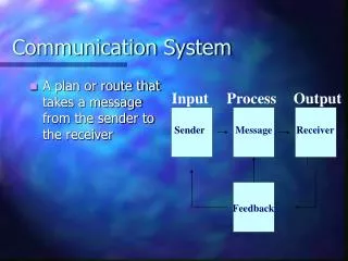
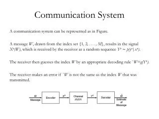
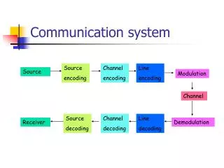
Communication System(Cont..) • source: originates a message • transmitter: converts the message into a signal that can be transmitted over a channel • Channel: transport of the signal over a certain medium (e.g. wire, optical fiber or a radio link) • Receiver: converts the received signal back into a readable message • Sink/destination: end user scheme of a simplified communication system
Communication System • channel encoder: encodes the signal pulses in a format that is required by the channel • protocol: controls start, end of transmission and error recovery by adding additional bits for error detection and/or correction • noise: inside the channel the signal is disturbed by noise scheme of a (nearly) complete digital communication system • adc(analog/digital converter): converts the physical analog signal into a digital electronic signal • source encoder: encodes the data in a format that removes redundancy and irrelevant information • modulator: adaptation of the frequency according to the channel characteristics • on the receiver side all transformation steps must be reversed
Communication System(Cont..) • • In a realistic channel a signal is disturbed by: • noise: random and unpredictable modifications of the signal amplitude • thermal noise, caused by random movements of electrons in conductors • external noise, caused e.g. by interference with other channels • attenuation: the amplitude of the signal decreased caused by the resistance of the channel • the maximum length is restricted; amplifiers are required in certain distances! • distortion: the distortion depends on the frequency, different signal frequencies suffer different signal distortion.
SIGNALS • A signal is the form in which data is transmitted. Its describes the behavior of data Mathematical representation of a signal • Signal can be Mathematically represented by a dependent variable and independent variable x(t) = t2 + 1 • Also a signal could be represented by sinusoidal wave x(t) = Asin(2πft + θ ) • Parameters of the signal are: amplitude, phase and frequency • Deterministic and random signals
Signal parameters • Sine Wave • Amplitude ,Frequency Phase
The sine wave or sinusoid • The sine wave or sinusoid is a mathematical function that describes a smooth repetitive oscillation. It occurs often in pure mathematics, as well as physics, signal processing, electrical engineering and many other fields. Its most basic form as a function of time (t) is: • where: • A, the amplitude, is the peak deviation of the function from its center position. • ω, the angular frequency, specifies how many oscillations occur in a unit time interval, in radians per second • φ, the phase, specifies where in its cycle the oscillation begins at t = 0. • When the phase is non-zero, the entire waveform appears to be shifted in time by the amount φ/ω seconds. A negative value represents a delay, and a positive value represents a "head-start". A cosine wave is said to be "sinusoidal", because cos(x) = sin(x + π / 2), which is also a sine wave with a phase-shift of π/2.
Three sine waves with the same amplitude and frequency, but different phases Phase describes the position of the waveform relative to time 0.
Time and Frequency Domain • Composite Signals The time-domain and frequency-domain plots of a sine wave A complete sine wave in the time domain can be represented by one single spike in the frequency domain.
The time domain and frequency domain of three sine waves A single-frequency sine wave is not useful in data communications; we need to send a composite signal, a signal made of many simple sine waves.
Fourier Analysis According to Fourier analysis, any composite signal is a combination of simple sine waves with different frequencies, amplitudes, and phases. If the composite signal is periodic, the decomposition gives a series of signals with discrete frequencies; if the composite signal is nonperiodic, the decomposition gives a combination of sine waves with continuous frequencies.
A composite periodic signal Decomposition of a composite periodic signal in the time and frequency domains
Bandwidth The bandwidth of periodic and nonperiodic composite signals The bandwidth of a composite signal is the difference between the highest and the lowest frequencies contained in that signal.
Classifications of Signals • Continuous-Time vs. Discrete-Time • determined by whether or not the time axis (x-axis) is discrete (countable) or continuous • A continuous-time signal will contain a value for all real numbers along the time axis. • In contrast to this, a discrete-time signal is often created by using the sampling theorem to sample a continuous signal, so it will only have values at equally spaced intervals along the time axis.
Analog versus Digital • The difference between analog and digital is similar to the difference between continuous-time and discrete-time. • Analog corresponds to a continuous y-axis, while digital corresponds to a discrete y-axis. An easy example of a digital signal is a binary sequence, where the values of the function can only be one or zero.
Analog versus Digital Communication • Analog messagesare characterized by data with values from a • continuous range. • they have an indefinite number of values • there is an indefinite number of possible waveforms in a time interval. • Digital messagesare constructed from a finitenumber of symbols. • Mostly only a binary message is used. Different kinds of digital signal are treated identically.
Analog versus Digital communication (Cont’d) • Analog example: • Digital example: (k=2)
Analog versus Digital communication (Cont’d) • In a binary digital signal a "1" can be transmitted by an electric pulse of amplitude A/2, a "0" by a pulse of amplidude –A/2 • Receiver must only decide, if the signal level is above 0 or not: • transmitted signal • received distorted signal without noise • received distorted signal with noise • regenerated signal
Analog versus Digital communication (Cont’d) • Distorted and noisy digital signals can mostly be recovered without error • if repeaters are placed along a digital communication path, they can regenerate the signal before amplifying it. • digital messages can be reliably transmitted over long distances • Distorted and noisy analog signals cannot be recovered • there is no way to avoid accumulation of noise and distortion • amplification does not help because both signal and noise are amplified in the same proportion! • analog messages can only be transmitted over short distances if a high quality is desired
Classification of signals Deterministic signal: No uncertainty with respect to the signal value at any time. each value of the signal is fixed and can be determined by a mathematical expression, rule, or table. future values of the signal can be calculated from past values with complete confidence. Random signal: Some degree of uncertainty in signal values before it actually occurs. Thermal noise in electronic circuits due to the random movement of electrons Reflection of radio waves from different layers of ionosphere
(a) Deterministic Signal (b) Random Signal
Classification of signals … Periodic and non-periodic signals Periodic signals repeat with some periodT, while aperiodic, or non-periodic, signals do not A periodic signal A non-periodic signal
Classification of Signals • Causal vs. Anticausal vs. Noncausal • Causal signals are signals that are zero for all negative time, while anticausal are signals that are zero for all positive time. Noncausal signals are signals that have nonzero values in both positive and negative time (b) An anticausal signal (a) A causal signal (c) A noncausal signal
Classification of Signals • Even vs. Odd • An even signal is any signal f such that f(t) =f(−t) . • Even signals can be easily spotted as they are symmetricaround the vertical axis. • An odd signal, on the other hand, is a signal fsuch that f(t) =−(f(−t) ) (a) An even signal (b) An odd signal
Classification of Signals • Right-Handed vs. Left-Handed • A right-handed signal and left-handed signal are those signals whose value is zero between a given variable and positive or negative infinity. (a) Right-handed signal (b) Left-handed signal
Signal Operations • Time Shifting • the shifting of a signal in time. This is done by adding or subtracting the amount of the shift to the time variable in the function. Subtracting a fixed amount from the time variable will shift the signal to the right (delay) that amount, while adding to the time variable will shift the signal to the left (advance). 33
Signal Operations • Time Scaling • Time scaling compresses and dilates a signal by multiplying the time variable by some amount. If that amount is greater than one, the signal becomes narrower and the operation is called compression, while if the amount is less than one, the signal becomes wider and is called dilation 34
Signal Operations • Time Reversal • What happens when the time variable is multiplied by a negative number? The answer to this is time reversal. This operation is the reversal of the time axis, or flipping the signal over the y-axis. 35
Signal Energy and Signal Power • Size • The idea of the "size" of a signal is crucial to many applications. It is nice to know how much electricity can be used in a defibrillator without ill effects, for instance. It is also nice to know if the signal driving a set of headphones is enough to create a sound. For this reason, it is convenient to quantify this idea of "size". This leads tothe ideas of signal energy and signal power.
Signal Energy • signal is a function of varying amplitude through time, so a good measurement of the strength of a signal would be the area under the curve. • However, this area may have a negative part. This negative part does not have less strength than a positive signal of the same size • The negative part cancels the positive Figure 1 • This suggests either squaring the signal or taking its absolute value, then finding the area under that curve Figure 2
Signal Energy Fig 1 Fig 2 • A signal is an energy signal if, and only if, it has nonzero but finite energy for all time: • In integral form it can be represented as
Signal Power • We know that the energy of a signal is given by squaring the signal or taking its absolute value, then finding the area under that curve • But what if the signal does not decay? In this case we have infinite energy for any such signal. • Power is defined as energy over a specific time interval and is given by • A signal is a power signal if, and only if, it has finite but nonzero power for all time: • And in integral form it can be given as General rule: Periodic and random signals are power signals. Signals that are both deterministic and non-periodic are energy signals.
SIGNAL TO NOISE RATIO Two cases of SNR: a high SNR and a low SNR
SIGNAL TO NOISE RATIO The power of a signal is 10 mW and the power of the noise is 1 μW; what are the values of SNR and SNRdB ? Solution The values of SNR and SNRdB can be calculated as follows: The values of SNR and SNRdB for a noiseless channel are We can never achieve this ratio in real life; it is an ideal.
DATA RATE LIMITS A very important consideration in data communications is how fast we can send data, in bits per second, over a channel. Data rate depends on three factors: 1. The bandwidth available 2. The level of the signals we use 3. The quality of the channel (the level of noise) • We consider two laws • Nyquist Law • Shannon Law Increasing the levels of a signal may reduce the reliability of the system.
Nyquist Law And Shannon Law Nyquist Law : Shannon’s Law : Where C= Data rate of the channel B= Bandwidth of the signal And L= Number of levels in the signal The Shannon capacity gives us the upper limit; the Nyquist formula tells us how many signal levels we need. • For Noiseless Channel: • We use Nyquist Bit Rate • For Noisy Channel: • We use Shannon Capacity • We also can use Both Limits
Nyquist Law Examples 1.Consider a noiseless channel with a bandwidth of 3000 Hz transmitting a signal with two signal levels. The maximum bit rate can be calculated as 2.Consider the same noiseless channel transmitting a signal with four signal levels (for each level, we send 2 bits). The maximum bit rate can be calculated as 3.We need to send 265 kbps over a noiseless channel with a bandwidth of 20 kHz. How many signal levels do we need? using Nyquist formula as shown: Since this result is not a power of 2, we need to either increase the number of levels or reduce the bit rate. If we have 128 levels, the bit rate is 280 kbps. If we have 64 levels, the bit rate is 240 kbps.
Shannon’s Law Examples 1.Consider an extremely noisy channel in which the value of the signal-to-noise ratio is almost zero. In other words, the noise is so strong that the signal is faint. For this channel the capacity C is calculated as This means that the capacity of this channel is zero regardless of the bandwidth. In other words, we cannot receive any data through this channel. 2.We can calculate the theoretical highest bit rate of a regular telephone line. A telephone line normally has a bandwidth of 3000. The signal-to-noise ratio is usually 3162. For this channel the capacity is calculated as This means that the highest bit rate for a telephone line is 34.860 kbps. If we want to send data faster than this, we can either increase the bandwidth of the line or improve the signal-to-noise ratio.
Shannon’s Law Examples 3.The signal-to-noise ratio is often given in decibels. Assume that SNRdB = 36 and the channel bandwidth is 2 MHz. The theoretical channel capacity can be calculated as 4.For practical purposes, when the SNR is very high, we can assume that SNR + 1 is almost the same as SNR. In these cases, the theoretical channel capacity can be simplified to For example, we can calculate the theoretical capacity of the previous example as
Example We have a channel with a 1-MHz bandwidth. The SNR for this channel is 63. What are the appropriate bit rate and signal level? Solution First, we use the Shannon formula to find the upper limit. The Shannon formula gives us 6 Mbps, the upper limit. For better performance we choose something lower, 4 Mbps, for example. Then we use the Nyquist formula to find the number of signal levels.