Download
1 / 28
280 likes | 442 Views
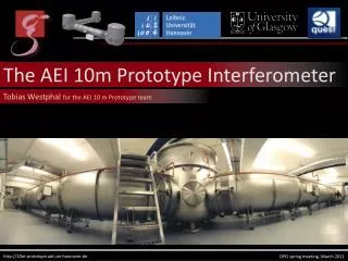
The AEI 10m Prototype Interferometer. Tobias Westphal for the AEI 10 m Prototype team. http://10m-prototype.aei.uni-hannover.de. DPG spring meeting, March 2011. Why to build another PT. Ultra-low displacement-noise test environment To probe at and beyond the Standard Quantum Limit (SQL)

E N D
The AEI 10m Prototype Interferometer Tobias Westphalfor the AEI 10 m Prototype team http://10m-prototype.aei.uni-hannover.de DPG spring meeting, March 2011
Whytobuildanother PT • Ultra-low displacement-noise test environment • To probe at and beyond the Standard Quantum Limit (SQL) • equivalent Heisenberg limit for 100g test masses • Thermal noise interferometer • Other experiments within QUEST (for e.g. LISA or GRACE follow on) • Entanglement of macroscopic test masses (a bit further down the road…) Maximal overlap with GEO-HF subsystems • Develop and prove as many of the techniques needed for gravitational wave detector upgrades as possible (e.g. laser, digital control infrastructure) • Provide training for people who will install upgrades to and run GEO-HF
SQL interferometerlayout Optional: Signal recycling ~8W @ 1064nmfibercoupled 10m Fabry-Perot arm cavity Finesse ca. 700 Tap off ~130mW Optional: Power recycling Frequency referencecavity Length: 12m Finesse: ca. 7500 Triplependulumsuspension Mirror mass: 860g 100g Mirrors monolithicsilicasuspensions Anti-resonant Fabry-Perotcavity as compound end mirror
Squeeze-in tanks Learnfromexperience! Earlierdays (GEO600 design): Not very versatile REALLY uncomfortable towork in
Walk-in tanks 100mm flanges to fit feedthroughs 600mm flanges to fit viewports Walk-in door 100mm flanges to fit feedthroughs
Ultra-high vacuum system Tubes: 1.5m Ø Tanks: 3.4m tall 3m Ø 10-6mbar after about 12 hours • 100m³ Volume • 22t stainlesssteel • 170l/s screw pump (roughing) • 2x 2000l/s turbo pump (main) • 2x scroll pump (backing & differential) • Metalgasketsbelow 600mm • Double O-ring differentiallypumped
Slicedopen Optical benches in thetanks Passive seismicisolation Activeintertablestabilisation
Table subsystems Inverted pendulum Accelerometer Geometric antispring Vertical motorized blade Optical table Filter support Base plate LVDT / Actuator Tilt stabilisation Horizontal motorized blade
GAS filter (verticalisolation) Top view Side view Featuring very soft potential → large isolation Huge loading capabilities
Estimated motion micro-seismic anthropogenic 60dB 70dB
Vertical isolation (measured) ← GAS-resonance frequency ca. 440mHz without magic wand off-centered accelerometer 7dB shaker structure
Estimated differential motion Inter table Activeisolation Passive isolation
Low freqency active isolation Stabilized intertable Activeisolation Passive isolation SPI Accelerometers LVDT`s
Suspension platforminterferometer Goal: Stabilize inter table motion 100pm/√Hz, 10nrad/√Hz @ 10mHz Based on LISA Pathfinder experience: Heterodyne Mach-Zehnder interferometer with unequal arm length (by 23m) Iodine-stabilised Nd:YAG (frequency noise) Optics bonded onto low CTE plate (thermal drifts) Digital signalprocessing (FPGAs)
Digital controlsystem • Analog world • Digital world • User world • Giveserrorsignals • Carriesactuation out • Changes • Getdata Experiment Sensors & actuators Front-end Digital filters Workstation ADC/DAC 6 x 32channel PCI-X DA/AD & DIO Fieldboxes Signal conditioning AA/AI filters GPS timing Frame builder Storage Based on realtime LINUX Runs EPICS software
Laser: 35W @ 1064nm 99% in TEM00 Pump diode: • 808nm, 45W • 400µm Øfiber coupled,NA=0,22 24W measurement TEM00 model Amplifier: • 38W for 2W seed and 150W pump Normalized power Frequency [FSR] Crystals: 3 x 3 x 10mm3 Nd:YVO4 8 mm 0,3% doped, 2mm endcap
Mirrorsuspensions Frequency reference cavity: Three horizontal, two vertical stages 850g per stage (mirror 10cm x 5cm) Steel wires, last stage 55µm Ø Local control and alignment control at uppermost stage (fast alignment is done at steering mirrors) Interferometer optics: Three horizontal stages, two vertical stages 100g per stage (mirror ca. 2“ x 1“) All silica last stage, 4 filaments of 20µm Ø
Where does coating noise appear? Coating noise Reflectivity N N • High reflectivecoatingshave lots ofcoatinglayers • Few layers medium R, low CTN • Many layers high R, high CTN • Let‘s separate reflectivity and losses!
Khalili cavity IETM EETM (2n+1) l/2 • One HR mirrortwomirrors: • Medium reflectivity: ca. 50% (IETM) • High reflectivity: 99.99% (EETM) • Factor 1.6 reductionofcoating thermal noise
Sensitivitywithdoping & Khalili • Titanium
The team http://10m-prototype.aei.uni-hannover.de • Ken Strain: Scientific leader • Stefan Goßler: Coordinator • Gerhard Heinzel: LISA/LPF related experiments • Yanbei Chen, KentaroSomiya, Stefan Danilishin: Experiment design, noise analysis • Roman Schnabel: Squeezing and QND experiments • HaraldLück: Vacuum system and GEO 600 related experiments • Hartmut Grote: Electronics and GEO 600 related experiments • GEO operators: Filter design and construction, environmental monitoring • Andreas Weidner: Electronics design • KasemMossavi: Vacuum system and pumps control • Jens Breyer: Mechanical design • BennoWillke, Jan HendrikPöld, Christina Bogan: High power laser • GerritKühn, Michael Born, Martin Hewitson: Real time control system • Alessandro Bertolini, Alexander Wanner: Isolation tables • Katrin Dahl: SPI • Fumiko Kawazoe: Frequency reference cavity • Stefan Hild, Sabina Huttner, Christian Gräf:Interferometric sensing & control • Giles Hammond, Tobias Westphal: Monolithic suspensions • Gerald Bergmann: Commissioning See poster Christian Gräf Q57.83 16:30