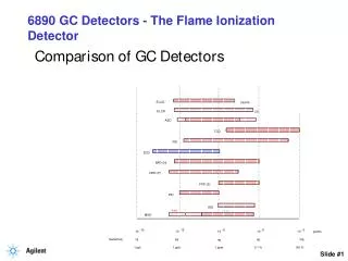
Flame Ionization Detector Overview
The Flame Ionization Detector responds to any molecule with a carbon-hydrogen bond, but its response is either poor or nonexistent to compounds such as H2S, CCl4, or NH3. Since the FID is mass sensitive, not concentration sensitive, changes in carrier gas flow rate have little effect on the detector response. For more information, please visit - http://quadrexcorp.com/<br>

Flame Ionization Detector Overview
E N D
Presentation Transcript
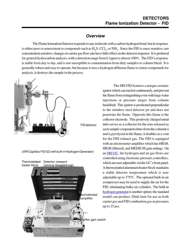
DETECTORS Flame Ionization Detector - FID Overview The Flame Ionization Detector responds to any molecule with a carbon-hydrogen bond, but its response is either poor or nonexistent to compounds such as H2S, CCl4, or NH3. Since the FID is mass sensitive, not concentration sensitive, changes in carrier gas flow rate have little effect on the detector response. It is preferred for general hydrocarbon analysis, with a detection range from 0.1ppm to almost 100%. The FID’s response is stable from day to day, and is not susceptible to contamination from dirty samples or column bleed. It is generally robust and easy to operate, but because it uses a hydrogen diffusion flame to ionize compounds for analysis, it destroys the sample in the process. The SRI FID features a unique ceramic ignitor which can run hot continuously, and prevent the flame from extinguishing even with large water injections or pressure surges from column backflush. This ignitor is positioned perpendicular to the stainless steel detector jet and does not penetrate the flame. Opposite this flame is the collector electrode. This positively charged metal tube serves as a collector for the ions released as each sample component elutes from the column(s) and is pyrolyzed in the flame; it doubles as a vent for the FID exhaust gas. The FID is equipped with an electrometer amplifier which has HIGH, HIGH (filtered), and MEDIUM gain settings. On an SRI GC, the hydrogen and air gas flows are controlled using electronic pressure controllers, which are user adjustable via the GC’s front panel. A thermostatted aluminum heater block maintains a stable detector temperature which is user adjustable up to 375oC. The optional built-in air compressor may be used to supply the air for the FID, eliminating bulky air cylinders. The built-in hydrogen generator is another option: the standard model can produce 20mL/min for use as both carrier gas and FID combustion gas at pressures up to 25 psi. FID detector (SRI Capillary FID GC with built-in Hydrogen Generator) Thermostatted heater block Detector viewport (remove Swagelok cap) Flameport Collector electrode Electrode lead to amplifier Ceramic ignitor H2 in Amplifier gain switch Air in
DETECTORS FID - Flame Ionization Detector Theory of Operation In the SRI FID, the carrier gas effluent from the GC column is mixed with hydrogen, then routed through an unbreakable stainless steel jet. The hydrogen mix supports a diffusion flame at the jet’s tip which ionizes the analyte molecules. Positive and negative ions are produced as each sample component is eluted into the flame. A collector electrode attracts the negative ions to the electrometer amplifier, producing an analog signal for the data system input. An electrostatic field is generated by the difference in potential between the positively charged collector electrode and the grounded FID jet. Because of the electrostatic field, the negative ions have to flow in the direction of the collector electrode. The FID hydrogen diffusion flame
The ratio of air to hydrogen in the combustion mixture should be approximately 10:1. If the carrier flow is higher than normal, the combustion ratio may need to be adjusted. Flow is user adjusted through the Electronic Pressure Controllers (EPC); the rates used to generate test chromatograms at the factory are printed on the right side of the GC in the flow rate chart. The FID temperature must be hot enough so that condensation doesn’t occur anywhere in the system; 150oC is sufficient for volatile analytes; for semi-volatiles, use a higher temperature. In addition to using the ignitor to light the flame, it may be left on at an intermediate voltage level to prevent flameout (-750 or 7.5 volts). The ignitor is very durable and will last a long time, even at high temperatures. FID detector schematic