HIE-ISOLDE SC-RF Cavities
320 likes | 480 Views
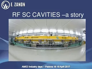
HIE-ISOLDE SC-RF Cavities. Sergio Calatroni. HIE linac staged installation. 3 stages installation. 1.2 MeV/u. 3 MeV/ u. 5.5 MeV/ u. 10 MeV/ u. From: M. Pasini. Why Nb /Cu cavities?. Mechanical stability (reduction of microphonics and sensitivity to He bath pressure)

HIE-ISOLDE SC-RF Cavities
E N D
Presentation Transcript
HIE-ISOLDE SC-RF Cavities Sergio Calatroni
HIE linac staged installation 3 stages installation 1.2 MeV/u 3 MeV/u 5.5 MeV/u 10 MeV/u From: M. Pasini Sergio Calatroni - 15.6.2009
Why Nb/Cu cavities? • Mechanical stability (reduction of microphonics and sensitivity to He bath pressure) • Simpler cryostat: no magnetic shielding, conduction cooling • CERN experience (LEP, LHC, R&D) • Largest experience of niobium sputtering for cavities • Extensive experience of copper surface treatments • Available experience from INFN-LNL • Choice of biased diode sputtering as baseline • EuCARD WP10.4.3: development of sputter technology (magnetron sputtering, Hipims) for QWR, aimed at HIE-ISOLDE Sergio Calatroni - 15.6.2009
BCS surface resistance Performance will be dominated by Rres which is expected to be acceptable for our target parameters. Our goal < 75 nOhm @ nominal field Sergio Calatroni - 15.6.2009
Low-β and high- β cavities Sergio Calatroni - 15.6.2009
Mechanical design criteria • Avoid any brazing or annealing: • Negative experience from LNL for coating performance • Loss of mechanical properties • Cu-OFE C10100 cold worked (rolled sheets, forged billets). • Choice of manufacturing 100% at CERN workshop, thus using only available techniques: • Long distance EB welding possible • Inner EB welding not possible • Deep drawing preferred over 3D machining for beam ports. Sergio Calatroni - 15.6.2009
FEM analyses Heat flux input and resulting temperature distribution in the cavity, considering the thermal conductivity of copper RRR=100 and pool boiling cooling in convection and nucleate boiling regimes. First and second vibration mode shapes and corresponding frequencies. Sergio Calatroni - 15.6.2009
Inner and outer cylinders Sergio Calatroni - 15.6.2009
Outer cylinder Sergio Calatroni - 15.6.2009
Inner cylinder Sergio Calatroni - 15.6.2009
Manufacturing sequence 13 3 2 1 7 11 6 8 Manufacturing of central tube Manufacturing of head E-beam welding of the 3 parts of inner conductor Fine machining of inner conductor Drilling of beam line Final long-distance e-beam welding E-beam welding of top flange ensemble 9 9 10 • Rolling of half tubes, longitudinal welding, rough machining • Machining of end piece • E-beam welding • Fine machining of inner surface • “Bossage” and machining of beam ports • Manufacturing of baseplate of inner conductor 12 4 5 Sergio Calatroni - 15.6.2009
Welding test: 1000 mm distance e-beam Roughness measured after welding and SUBU chemical polishing, 20 µm removed Achieved Ra better than 0.8 µm, target value based on LEP/LHC/1.5 GHz CERN experience Sergio Calatroni - 15.6.2009
Beam ports Obtained shape accuracy better than 0.1 mm Sergio Calatroni - 15.6.2009
Design of bias sputter coating system Vacuum tank Cavity Thermal shield Cooling Sputtering cathode Cooling feedthrough HV feedthrough Pump connection Sergio Calatroni - 15.6.2009
Coating assembly: cathodes and cavity cooling Sergio Calatroni - 15.6.2009
- 80 V Object - cavity Kr 0 V Kr+ Kr+ e Kr + Sputter cathode Nb - 1000 V Vacuum pump Details of diode bias sputtering Target thickness: 1 µm (20x ) Cavity cooled during coating Sergio Calatroni - 15.6.2009
Tests on samples Quartz samples for thickness calibration, RRR, Tc Sergio Calatroni - 15.6.2009
First plasma (Kr as sputter gas) Sergio Calatroni - 15.6.2009
Foreseen coating procedure and quality controls • Cavity manufacturing • Metrology checks, US and X-ray of weldings, roughness guaranteed by respect of manufacturing procedure (checked on samples) • Surface treatment: SUBU 20 µm • Check by weigh loss and visual inspection • Coating: • Quality checked by RRR and Tc on quartz samples • Control and reproduction of sputtering parameters: Kr pressure, sputter V-I, bias voltage, cavity temperature. • (Water rinsing: resistivity, particle count and TOC of output water) Sergio Calatroni - 15.6.2009
Surface treatment Sergio Calatroni - 15.6.2009
CFD studies of chemical polishing bath The velocity of the fluid close the bottom wall of the cavity is quite uniformly distributed. The values obtained are comprised between 0.04 m/s and 0.06 m/s. SUBU: Sulfamic acid (H3NO3S) 5 g/L, H2O2 5% vol, n-butanol C4H10O 5% vol, di-ammonium citrate (C6H14N2O2) 1 g/L. Chemical polishing is carried out at 72 °C and is preceded and followed by washing with H3NO3S. Sergio Calatroni - 15.6.2009
Study of rinsing system (after CP/ after coating) Sergio Calatroni - 15.6.2009
Study of clean room assembly 1.Installation Bride de Base 2. Installation Dépôt Niobium 3. Enlèvement Rehausses 4. Installation Cavité Ø300 Sens Montage 5. Installation Tank Inférieur 6. Installation Tank Supérieur 7. Enlèvement Rehausses 8. Equipement prêt pour sortir From: G. Villiger Sergio Calatroni - 15.6.2009
RRR measurements System tested for preliminary Nb coating run of RF tuning plate Sergio Calatroni - 15.6.2009
Study of RF tuning plate (in construction) Sergio Calatroni - 15.6.2009
FEM analyses Displacement: +15 mm (up) -5 mm (down) (Apparent concentration of stresses due to probable numerical errors. Plastification would anyhow spread the stress around) Sergio Calatroni - 15.6.2009
Conclusions and outlook I • Cavity prototype fabricated. • Tooling an teething problems ironed out • 5 more pre-series in fabrication (one full cryomodule) • Tuning plate, couplers in fabrication • Coating development: • Study I-V curves as a function of sputter gas pressure, bias voltage. • Characterize RRR of samples. • Optimize geometry if necessary • Surface treatment optimization: • Tests on samples and on dummy cavity successful • Waiting for first cavity treatment • Samples characterization setup ready • Plus access to CERN facilities: SEM, XPS, etc. Sergio Calatroni - 15.6.2009
Conclusions and outlook II • First cavity coating expected during July/August 2009 • Optimization work has to proceed fast • All tooling is ready (for clean room assembly, etc.) except for ultrapure water rinsing. This operation will be done by hand, series tooling delayed after first prototype. • RF test not available at CERN in the short term • Goal: achieve nominal specifications by end 2009 Sergio Calatroni - 15.6.2009
Finally • Main contributors • Mechanical design: Philippe Trilhe, Franck Thierry, Philippe Perret, Gilles Villiger, Delio Duarte Ramos, Luca Gentini, Ricardo De MoraisAmaral • Mechanical fabrication: Thierry Tardy, Christian Saint-Jal, Jean-Marie Geisser, Jean-Pierre Brachet, Pierre Moyret, Rene Claret, Ahmed Cherif, Dominique Pugnat. • Surface treatments: Leonel Ferreira, Serge Forel, Marc Thiebert • Coating: Giulia Lanza, Antonio Mongelluzzo, Jean Cave, Anna Gustafsson • Cryolab: Tapio Niinikoski, Friedrich Haug, Sebastien Prunet, Laetitia Dufay-Chanat Sergio Calatroni - 15.6.2009