Download
1 / 19
190 likes | 206 Views
Measurement of Ion Density i n Magnetospheric Plasma Plumes. B J F raser 1 , H J Singer 2 , J Goldstein 3 , D L Gallagher 4 , M Thomsen 5 1 CRC for Satellite Systems, School of Mathematical and Physical Sciences, University of Newcastle , Callaghan, NSW 2308 Australia

E N D
Measurement of Ion Density in MagnetosphericPlasma Plumes B J Fraser1, H J Singer2, J Goldstein3, D L Gallagher4, M Thomsen5 1CRC for Satellite Systems, School of Mathematical and Physical Sciences, University of Newcastle , Callaghan, NSW 2308 Australia 2NOAA/SEC, 325 Broadway, Boulder, CO 80305 USA 3Department of Physics and Astronomy, Rice University, Houston, TX 4Space Science Department, Marshall Space Flight Centre, National Space Science & Technology Center, Huntsville, AL 5Los Alamos National Laboratory, Los Alamos, NM
Outline • Look at EMIC waves in plasma plumes. • Use spectra of EMIC waves propagating in a multi-ion plasma to determine fractional plasma constituents (H+:He+:O+). • Determine these using IMAGE-EUV, LANL, GOES satellite data
Plasma Density Constituents • Radial ion plasma density profile, typically used to display the presence of the plasmapause, is generally deduced from electron or H+ ion measurements [Carpenter and Anderson, 1992; Chappell et al., 1970]. • Recently the dynamics of the plasmapause have been studied using the IMAGE EUV instrument which indirectly measures the total column density of He+ ions [Burch et al., 2001]. • It is important to intercompare these different measurements in order to define their response at the plasmapause and within the plasmasphere. • Ion composition measurements have shown He+ is the second most abundant ion in the plasmasphere, after H+ with an average relative concentration of 20%, but is sometimes comparable to that of H+ [Newberry, 1989].
Plasma Density Constituents (2) • Just inside the plasmapause heavy ion (O+, O+ + and N+) densities have been found to increase by a factor of 10 or more when there is no corresponding variation in H+ or He+ ions. • This is commonly called the oxygen torus due to the dominance of oxygen ions [Roberts et al., 1987]. Horwitz et al. [1984] showed that the ion composition in the plasmasphere and near the plasmapause is highly variable and typically includes H+, He+, He++, O+ and O++ ions. • Therefore, mass loading will vary radially and the assumption of a constant mass loading, as assumed by Moore et al. [1987] and Fraser et al. [1988] and others in the past, is not appropriate.
EMIC Waves and Plasma Structures • Plumes are associated with sub-auroral proton arcs seen in IMAGE-FUV (Immel et al., 2003). This supports the idea that the EMIC waves are pitch angle scattering keV protons into the loss cone giving rise to precipitation at low altitudes. • Recent IMAGE EUV data and GOES magnetometer that electromagnetic ion cyclotron waves (EMIC) are seen in association with enhanced plasma density structures identified as plumes (Fraser et al., 2005). • IMAGE-EUV measures the He+30.4nm emission and through modeling an He+pseudo-density is measured (Gallagher, private communication). This suggests that the EMIC waves are observed, at least, in a two component H+-He+plasma.
23 May 2001 IMAGE FUV-EUV Detached Proton Arc; Plasma Plume FUV sees arcs 1901-2327UT GOES-8 Footprint (T89 Kp=3) EUV plasmasphere
GOES-8 EMIC Waves 23 May 2001 1.0 Hn Hz 0 2310UT 2210
GOES-8 Spectral Analysis: 23 May 2001 2210-2310UT He-Hn He Pwr Pwr 1.0 Coherence Hn 0 Pwr LH 0 RH Crossphase 0 1.0 1.0 0 Frequency (Hz) Frequency (Hz)
EUV EUV
EMIC Waves and Radial Plasma Structures 1.0 1.0 G8 G10 Hn Hn Frequency Interference 0 0 23 24UT 18 20UT 14 15LT 13 15LT EUV Plasmapause 26 June 2001 18:20- 19:20UT G8 23:05-23:40UT G10 Maps from: Spasojevic et al. (2003) 26 June 2001 Figure 5
26 June 2001 2305-2335UT GOES-10 fHe fco Crosspower Hn-He (nT2/Hz) Coherence RH Phase LH 0 1.0 Hz
Dispersion Relations • In a two component plasma two emission bands are often seen due to the non-propagation stop-band in the dispersion relation. • The stopband width is related to the fractional abundance of He+in the plasma. When combined with LANL MPA plasma density data (H+, He+) it is possible to check the IMAGE psuedo-densities.
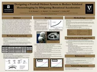
Plasma Density and Heavy Ions Dispersion relation Plasma plumes seen by IMAGE-EUV are a consequence of the He+ 30.4nm emission and indicate the presence of He+ in the plasma. Here EMIC waves are propagating in a multi-ion plasma (H+, He+) and a spectral slot should be seen in spectra G8: 23 May 2001 H+-He+ 1.0 1.0 G10 Hn Hn Hz fco fHe+ G10: 26 June 2001 0 0 2210 2310UT 23 24UT fco fHe+ fco=0.32Hz; fHe+=0.45Hz fco=0.30Hz; fHe+=0.42Hz β = 0.14 β = 0.13 Four other event measurements, including calculated f He+ from the total B field in addition to measuring from spectra, show the range β = 0.06 – 0.16 (6-16% He+) Non-propagation stopband betweenfco andfHe+ can be seen in spectra and is related to the He+ concentration through fco = (1 + 3β)fHe+ where β is the relative He+/H+ concentration (Young et al. 1981; Fraser 1985)
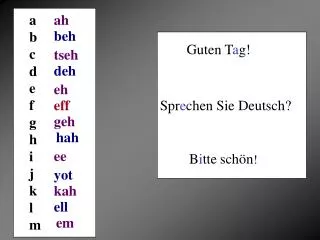
Plasma Density Measurements – H+ - He+ Ions Comparison of He+ densities derived from EMIC and LANL MPA ion data with computations from the Gallagher Pseudo-Density Model using IMAGE-EUV data
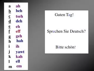
26 June 2001 2305-2335UT fO fco fHe fco Crosspower Hn-He (nT2/Hz) Coherence RH Phase LH 0 1.0 Hz Plasma Density Measurements – H+ - He+ - O+ Ions • Consider a 3-ion plasma: • If the oxygen propagation stopband can be identified in the EMIC wave spectra then the fractional O+ density () may also be determined. • With fco=0.33Hz; fHe+=0.47Hz fco=0.20Hz; fO+=0.08Hz β = 0.14 and = 0.10, or H++He++O+ = 50 cm-3 H+:He+:O+ = 38:7:5 cm-3 H++He++O+ = 90 cm-3 H+:He+:O+ = 68:13:9 cm-3 GOES-10
Plasma Diagnostics using EMIC Waves CRRES statistics August 1991 – October, 1992 Locally normalised wave frequency, X, versus L = Le – Lpp • Le and Lpp are the L values corresponding to the position of the wave occurrence and that of the plasmapause respectively. • L < 0 indicates that waves occur in the plasmasphere • L > 0 outside the plasmasphere, in the plasma trough.
Conclusions • EMIC waves are associated with plasma plumes extending out from the plasmapause to geostationary orbit. • Plume observed in Helium; LANL measures multi-ion density. • EMIC waves up to 1Hz are measured by GOES as they pass through a plasma plume. • The EMIC waves propagate in a 3 ion plasma and show spectral slot due to Helium and Oxygen non-propagation stop-bands. • With these data we can determine the ion densities. Caution: • Errors not considered • Spectral slots are probably determined by the source location. The source and/or GOES may be off the equator. • These are densities measured in plumes which have an enhanced density compared with the surrounding ambient plasma.