Download
1 / 85
850 likes | 870 Views
Explore GMPLS, G. ASON, and OIF UNI/NNI to delve into the evolution, protocols, standards, and interoperability of control planes in optical networks. Learn about Global Telecom Architecture and the collaboration between standards bodies.

E N D
Optical Control Plane Initiatives: GMPLS, G.ASON and OIF UNI/NNI Steve Cortez Lyndon Ong Ciena Corporation 7/21/2004 1:30 PM
Agenda • What is a Control Plane • Evolution from Telephony • Evolution from Packet • How it’s applied to Optical Networks • Control Plane Protocols • The different standards bodies and roles • GMPLS – core protocols • ASON extensions from ITU-T • OIF Implementation Agreements and Testing • Interoperability Demonstrations • Conclusion
What is the Control Plane? • Control planes are familiar ground for telephony • DTMF tones/In-band signaling • Signaling System 7/ISDN • ATM Signaling • Signaling supports connection control functions • Connection address and characteristics • Confirmation of setup and teardown • Routing and Discovery added
Examples • In-band signaling • Control carried in the same data stream as data • Examples: telephony tones/ring; IP control applications such as SIP; MPLS control protocols • Out-of-band signaling • Control carried in a separate logical or physical data stream • Examples: SS7 – a physically separate control network overlay for telephony network control
Routing and Discovery • ATM PNNI • PNNI – Private Network-Network Interface • ATM Forum-defined signaling/routing protocol for ATM networks • Completed circa 1996 • ATM PNNI extends traditional telephony protocols • Adds link state routing protocol to distribute topology information • Adds neighbor discovery mechanism • Connection setup supports loose or strict explicit routes (Designated Transit Lists) • The routing protocol supports multi-level hierarchy • Theoretical 104 levels of hierarchy • Automated methods for topology summarization
Evolution from the Packet Side • RSVP – Resource Reservation Protocol • Original RFC 2205 from IETF • Supports one-way reservation of router resources • Path still utilizes IP routing tables • Multipoint-to-multipoint capability through filtering controls
RSVP Evolution • MPLS • RSVP protocol used to assign labels to a flow (going back to Tag Switching) • MPLS-TE • RSVP protocol used with explicit source routing • GMPLS • Extensions to MPLS for circuit networks • TDM (SONET/SDH) switching • Lambda switching • Fiber switching • All lumped under the category of “optical” networks
Existing SONET/SDH/OTN Control Functions • Overhead Bytes • Performance monitoring • Fault notification/isolation • Ring/linear protection signals • Communications Channel • DCC – for SONET/SDH • GCC – for OTN • One option for “signaling channel”, other is external control network
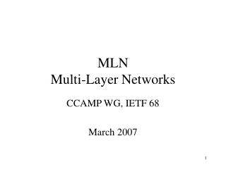
Summary - Control Plane Functions for Optical Networks • Automatic Neighbor Discovery • Allows a node to determine the identity of each neighboring node and the set of links that connect them. • Routing, or topology dissemination • Allows every node to automatically discover the complete network topology and resources • Signaling for Connection Provisioning • Allows the establishment and restoration of a path from one end of the connection
2. Global Topology Dissemination 1. Neighbor Discovery OUNI 3. Connection Request 4. Path Calculation (NE-based or EMS-based) 5. Establish Connection Sequence for Creating Connections Inventory & Resource Management NETWORK MGMT PLANE User User CONTROL PLANE DATA PLANE Dynamic Provisioning
Additional Functions • Services • Class of service • VPN • IP Integration • Advertisement of topology to routers • Common management view
Charter: Global Telecom Architecture and • Standards • Membership Fee: minimum $18,900/yr (31,500 Swiss Fr.) • No. of Members: 189 Member States + 434 Sector Members • Member Organizations: • Global Service Providers • PTTs, ILECs, IXCs • Telecom equipment vendors • Governments (e.g., US State Department) • Charter: Evolution of the • Internet (IP) Architecture • Membership Fee: None • Membership: Individuals – community model • Active Participants: • ISPs • Service Provider IP Divisions • IP/Ethernet Vendors • Charter: Development of Optical • Networking Products and Services • Membership Fee: $8000/yr • No. of Members: 312 Principal Members • Member Organizations: • PTTs, ISPs, ILECs, IXCs • Optical Networking Vendors Standards Bodies and Organizations
Standards Development Organizations (SDO) Interaction Requirements • Evolution towards convergence of requirements & protocols, enabling • Common/generic set of base protocols, with • Protocol extensions for optical transport domain application • Liaisons between all three SDOs on requirements and protocol work • IETF CCAMP and ITU-T joint design team on routing currently in progress ITU-T ASTN/ASON Umbrella OIF Implementation Agreements IETF GMPLS Umbrella Protocols
Optical Standards Efforts • IETF • GMPLS • Extensions to MPLS control protocols to support generic label control, including TDM, lambda and fiber “labels” • ITU-T • ASON • Automatic control of transport networks (SONET/SDH, OTN) using available control protocols • OIF • UNI and NNI Implementation Agreements • Agreed profiles and usage of standards at boundary points between and within carrier optical networks
GMPLS Overview • GMPLS extends MPLS/MPLS-TE control plane • Extensions primarily driven by characteristics of TDM, Lambda and Fiber Switching • GMPLS extends MPLS control planes to support ANY class of interfaces (i.e. layers) • PSC - Packet Switching Capable: IP/MPLS • L2SC - Layer-2 Switching Capable: ATM, FR, Ethernet • TDM - Time-Division Multiplexing: Sonet, SDH, G.709 ODUk • LSC - Wavelength Switching: Lambda, G.709 OCh • FSC - Fiber Switching
New Assumptions for GMPLS • Separate the Control Plane and Data Plane • MPLS • LSR combines control and IP data forwarding functions • Same port serves both data and control packets • GMPLS • LSR can be a switch with no IP (data plane) functions • Different ports or logical channels support data and control This is changed for GMPLS
Fully Out of Band Control Plane • Control Plane for TDM, LSC and FSC devices can be implemented in a separate network • Example: Fast Ethernet Control Plane
In-fiber Logically Separate Control Channel • Assumption is a SONET/SDH capable device • Recommendation is to use DCC (Data Communication Channel) bytes within SONET/SDH overhead • Section (RS) DCC is bytes D1, D2 and D3 (total 192kbps) • Line (MS) DCC is bytes D4-D12 (total 576kbps) SONET/SDH ADM LSR
GMPLS Mechanisms • GMPLS control plane architecture includes several extended MPLS-TE building blocks • Signalling Protocols: RSVP-TE and CR-LDP • Routing Protocols: OSPF-TE, ISIS-TE • New protocol for link management • Link Management Protocol (LMP) • LMP-WDM • Associated MPLS MIBs
GMPLS Signalling • Common signalling extensions • Generalized Label Request including • LSP Encoding Type • Switching Type • Payload Type (G-PID) • Upstream Label: bi-directional LSP • Label Set: tackle wavelength continuity in All Optical Networks • Suggested Label: to improve processing • Technology dependent extensions: Traffic parameters • TDM: SDH (ITU-T G.707) and Sonet (ANSI T1.105) • OTN: G.709 OTN (ITU-T G.709) including Pre-OTN
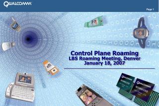
Path message flow, addressed directly to the unicast/multicast destination Resv message flow, hop-by-hop A B G C D F H E I RSVP – IP version Source Receiver 1 Receiver 2
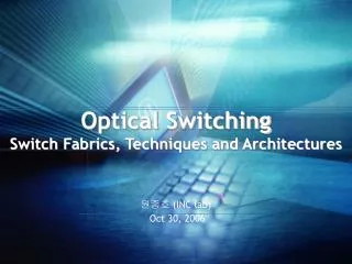
Path message flow, sent hop-by-hop to a single destination, with ERO = {A; B; C; D} Resv message flow, hop-by-hop RSVP – GMPLS version Source A C B D Point-to-point connection setup Periodic refresh still required Source assumed to know network topology Receiver
LSP Enc. type Switching Type G-PID Generalized Label Request Length Class-Num C-type 16 bits, Types = payload identifiers of the client layer for use by LSP end-point nodes. Examples of types include Asynch mapping of DS-1/T1, , FDDI, POS – Scrambled 16 bit CRC 8 bits, Encoding Types = packet, Ethernet, PDH, SONET/SDH, DW, , Fiber, FibreChannel 8 bits, Types = switching capabilities from routing (PSC, L2SC, TDM, LSC, FSC) G-PID is normally only examined at the egress
Bidirectional LSPs • Why bidirectional LSP set-up? • Reduces set-up latency, which could be significant for unidirectional path set-up for restoration • Reduces control messages (separate PATH and RESV for uni) • Simplifies route selection, avoids race conditions • Provides clean hop-by-hop paths for SONET/SDH-protected equipment • Presence of an Upstream label is trigger for bidirectional path set-up • Label contention resolved by local policy or Node with higher ID
Signal Type (8-bits) RCC (8-bits) NCC (16-bits) NVC (16-bits) Multiplier (16-bits) Transparency (32-bits) SDH/Sonet Traffic Parameters Signal Type • Elementary Component • E.g., SONET STS-1, SDH VC-4 Requested Contiguous Concatenation (RCC) • Flag field Profile (32 bits) Number of components (timeslots) • NCC: Contiguous concatenation • NVC: Virtual concatenation Multiplier (multiple connections) Transparency Profile (for further study)
SONET/SDH Label Definition 16 4 4 4 4 S U K L M U S U L M
Waveband Switching • Generalized label: Lowest in the band from sender’s perspective Waveband ID – 32 bits Start Label 32 bits Highest in the band from sender’s perspective End Label 32 bits • Can optimize OXC switching performance • Introduces another layer of hierarchy
Suggested Label • Upstream node sends preference to downstream node • Allows upstream node to start configuration • Reduces set-up latency • Faster restoration path set-up • Optimization that may be overridden by downstream node • Upstream node should not transmit data until downstream node sends corresponding label upstream
Inclusive or exclusive list, or range , fiber, etc. available for allocation Action - 8 bits Reserved - 10 bits Label type - 14 bits Subchannel 1 Subchannel N Label Set • Limits per-hop label choices • Usage examples: • Only certain range of s, or bands, can be transmitted • No -conversion is available over certain hops or entire path • -conversion must be limited to reduce optical impairments • Link ends support different ranges
GMPLS Signalling – Other • Explicit Label Control – allows precise label control • Protection information • Protection and restoration now under study • Administrative Status Information • Reflect the object back • Testing mode • Administratively down • Deletion in progress
GMPLS TE-Routing Extensions • GMPLS based on IP routing and addressing models • IPv4/v6 addresses used to identify PSC and non-PSC interfaces • Re-using of existing routing protocols enables: • benefits from existing intra and inter domain traffic-engineering extensions • benefits from existing inter-domain policy • Extend TE-Routing Attributes defined for MPLS-TE • For SDH/Sonet, G.709 OTN transmission technology, GMPLS-TE defines technology dependent TE extensions
Routing in GMPLS Networks • OSPF-TE and ISIS-TE extensions for GMPLS • Support for unnumbered links • Link protection type • Shared Risk Link Group Information • Interface switching capability descriptor • These extensions are additional sub-TLVs of: • TE Link TLV in OSPF-TE • Extended reachability TLV in ISIS-TE
OXC OXC OXC OXC MPLS TE RSVP TE Unified Control Plane GMPLS An LSP must start and end on the LSRs of the same type. IP Routing Protocols With Extensions OSPF, ISIS TE LSP Label Distribution Protocols CR LDP, RSVP TE SONET SDH NE Switch Switch Switch Switch Fiber Domain PSC Domain Forwarding Plane LSC Domain TSC Domain TE LSP Nested LSPs SONET SDH NE SONET SDH NE SONET SDH NE FA-LSC LSP Fiber Router Router Router Router Router Router Router Router FA-PCS LSP TDM OTN FA-TDM LSP Lambda LSP Packet GMPLS Domain Hierarchical LSPs
FA-LSC LSP Fiber FA-PCS LSP TDM FA-TDM LSP Lambda LSP Packet LSP Hierarchy • Enables aggregation of GMPLS LSP tunnels • Accomplished by • Inter-LSR LSP tunnel (FA-LSP) link is created • Ingress LSR injects link (FA-LSP) into IGP database • Other routers use the link in path calculation/setup • Other LSP tunnels are nested inside FA-LSP • FA LSP is policy driven • Advantages • Fewer high-order labels (e.g.lambdas) consumed • Nested LSPs can be of non-discrete bandwidth • FA-LSP can “hide” topology FA-LSP…Forwarding Adjacency LSP Nested LSPs
GMPLS TE-Routing Extensions • Flooding (dissemination) process within an OSPF area. • Link-state protocols use bundling capabilities, so Router TLV provides the Node ID • Technological hierarchies or LSP regions defined per interface Switching Capability (for instance, LSC) • Border and intermediate nodes can be multi-service devices i.e. more than one switching capability (for instance: Switching Capability = TDM and LSC)
Router OSPF Hello Local DB Synchronization Link State Update IETF OSPF Routing
OSPF Hello DB Synchronization Link state update • LSA contents: • Link interface identifiers • Link metric and color • Link switching type • Link available bandwidth • Link protection type • Link SRLG OSPF – GMPLS Version A C B D
Interface switching capability descriptor • Interfaces at each end of a link may be different • Interfaces on same node may be different • Descriptor may include additional information • Types:Additional information • PSC-1,2,3,4 min/max LSP bw, max MTU • TDM min/max LSP bw, signal type • LSC bw supported at given priority • A TE link label tuple determines link’s capability • [PSC, TDM] represents a TDM time slot • [TDM, LSC] represents an OXC port
Link Bundling Multiple s Multiple fibers Advertise every ? OR Advertise 1 Bundled Link! Adds scalability
Unnumbered Links - Routing • Local and remote interface identifiers are carried in sub-TLVs of the Link TLV, types 11 and 12 in OSPF-TE, extended IS reachability TLV in ISIS-TE LSR 2 LSR 3 assigns locally unique 32-bit “local” identifier to each link LSR 2 assigns locally unique 32-bit “local” identifier to each link LSR 3
Link Management Protocol - LMP • LMP Protocol provides: • IP Control Channel dynamic configuration • IP Control Channel maintenance (Hello Protocol) • ultra-fast (bi-directional sequencing) • reliable and robust • Link Property Correlation (Link bundling - TE Link) • Link Testing (optional) • Fault Management (optional) • detection (using LoS/LoL/etc.) • localization/correlation (alarm suppression) • reliable notification
T T P2 P1 R R A1 A2 LMP– Control Channel Maintenance • LMP adjacency • 1 or more Bi-directional CCs • IPCC independent of TE links • LMP Hello exchange • Unless other underlying keep-alive mechanism Hello (A1,P1) Hello (A2, P2) Hello Ack (A2, P2, A1, P1) Hello Ack (A1, P1, A2, P2)
P1 P10 P11 P2 P12 P3 A1 A2 LMP – Verify Link Connectivity • When using out of band control channel, need to test data bearing channels • Must be opaque (at least during the test!) BeginVerify (#, interval, data rate, etc.) BeginVerifyAck (VerifyID) Test Messages (P1, VID) TestStatusSuccess (P1, P10, VID) TestStatusAck (VID)
GMPLS Recovery Mechanisms • 4 Steps of Fault Management • Fault detection • Handle at the layer closest to failure • LOL, OSNR, at optical layer • BER, LOL at SONET/SDH layer • Fault Localization • Communication between nodes to “localize” failure (E.g. LMP, AIS) • Fault Notification • Communication between detecting node and node that institutes recovery (E.g. RSVP-Notify) • Fault Recovery
Path Protection & Restoration • Ingress node initiates recovery • New path can be dynamic or pre-calculated • Pre-calculated disjoint paths can use SRLG information • Protection paths can be flagged as secondary paths and used for pre-emptible traffic X C B D A Pre-emptible traffic Y X
Span Protection & Restoration • Can start restoration at an intermediate node • New “segment” can be dynamic or pre-calculated • Faster for large mesh networks C B D X A Y X
Path Notify Request: LSR A X LSR A Notify LSR A Notify Request Object and Notify Message in RSVP-TE • Optional Notify request objects can be carried in Path and Resv messages • Indicates address of the node to be notified of an LSP failure • Notify message serves to inform non-adjacent node of LSP-related events • Includes: • ERROR_SPEC defines error and IP address of failed link/detecting node • MESSAGE_ID if refresh reduction is supported

![GMPLS controlled dynamic optical core network simulation [COST266]](https://cdn1.slideserve.com/3287836/gmpls-controlled-dynamic-optical-core-network-simulation-cost266-dt.jpg)