Download
1 / 70
700 likes | 718 Views
Learn the functional characteristics of machine elements such as kinematic chains and inversions, and the principles of kinematics and dynamics. Study structures vs. machines, types of links, and constrained motions.

E N D
Course Objective: To Identify the functional characteristics of various machine elements • Course outline: Introduction, mechanisms • Assessment strategy : learning by doing activities
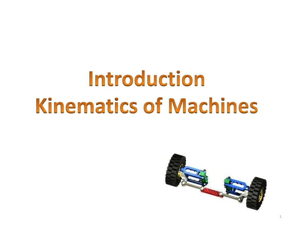
UNIT1: Introduction: Definitions Link or element, kinematic pairs, Degrees of freedom, Grubler’s criterion (without derivation), Kinematic chain, Mechanism, Structure, Mobility of Mechanism, Inversion,Machine. Kinematic Chains and Inversions: Inversions of Four bar chain; Single slider crank chain and Double slider crankchain.
Introduction • If a number of bodies are assembled in such a way thatthe motion of one causes constrained and predictable motion to the others, it is known as amechanism. • A mechanism transmits and modifies amotion. • A machine is a mechanism or a combination of mechanisms which, apartfromimpartingdefinitemotionstotheparts, alsotransmitsand modifies the available mechanical energy into some kind of desired work. • Thus, a mechanism is a fundamental unit and one has to start withits • study. • The study of a mechanism involves its analysis as well assynthesis. • Analysis is the study of motions and forces concerning differentparts of an existing mechanism, whereas synthesis involves the design of its differentparts. • In a mechanism, the various parts are so proportioned and related that themotionof oneimpartsrequisitemotionstotheothersandtheparts are able to withstand the forces impressed uponthem.
Kinematics: • Itdealswiththerelativemotionsofdifferentpartsof amechanism withouttaking into consideration the forces producing the motions. • Thus, it is the study, from a geometric point of view, to know the displacement, velocity and acceleration of a partof a mechanism. • Dynamics: • It involves the calculations of forces impressed upon differentparts of amechanism. • The forces can be either static ordynamic. • Dynamics is further subdivided into kinetics andstatics. • Kinetics is the study offorces when the body is in motion whereas statics deals with forces when the body isstationary.
Kinematic Link orElement • Eachpartofamachine,whichmovesrelativetosomeotherpart,is known as a kinematic link (or simply link) orelement. • A link may consist of several parts, which are rigidlyfastened together,sothattheydonotmoverelativetooneanother. • For example, in a reciprocating steam engine, as shown in Fig. 1, piston, piston rod and crosshead constitute one link ; connecting rod with big and small end bearings constitute a second link ;crank, crank shaft and flywheel a third link and the cylinder, engine frame and main bearings a fourthlink.
Types ofLinks Inordertotransmitmotion,thedriverandthefollowermaybeconnected by the following three types of links: Rigidlink. A rigid link is one which does not undergo any deformation while transmitting motion. Strictly speaking, rigid links do not exist. However, as the deformation of a connecting rod, crank etc. of a reciprocating steam engine is not appreciable, they can be considered as rigidlinks. Flexiblelink. A flexible link is one which is partly deformed in a manner not to affect the transmission of motion. For example, belts, ropes, chains and wires are flexible links and transmit tensile forcesonly. Fluid link. A fluid link is one which is formed by having a fluid in a receptacle and the motion is transmitted through the fluid by pressure or compression only, as in the case of hydraulic presses, jacks andbrakes.
Link orelement: • It is the name given to any body which has motion relative to another. All materials have some elasticity. A rigid link is one, whose deformations are so small that they can be neglected indetermining the motion parameters ofthe link. • Binarylink:Linkwhichisconnectedtootherlinksattwopoints. (Fig.a) • Ternarylink:Linkwhichisconnectedtootherlinksatthreepoints. (Fig.b) • Quaternarylink:Linkwhichisconnectedtootherlinksatfourpoints. (Fig.c)
Structure • It is an assemblage of a number of resistant bodies (known as members) having no relative motion between them and meant for carrying loads having straining action. A railway bridge, a rooftruss, machine frames etc., are the examples ofa structure. • Difference Between a Machine and aStructure • The following differences between a machine and a structure are importantfromthesubjectpointofview: • The parts of a machine move relative to one another,whereas the • membersofastructuredonotmoverelativetooneanother. • A machine transforms the available energy into some usefulwork, whereas in a structure no energy is transformed into usefulwork. • The links of a machine may transmit both power and motion,while • the members of a structure transmitforces only.
Thetwolinksorelementsofamachine,whenincontactwitheachother,aresaid to form a pair. If the relative motion between them is completely or successfully constrained(i.e.inadefinitedirection),thepairisknownaskinematicpair. Types of ConstrainedMotions Followingarethethreetypesofconstrainedmotions: 1. Completely constrained motion Whenthemotionbetweenapairislimitedtoadefinitedirectionirrespective of the direction of force applied, then the motion is said to be a completely constrainedmotion. For example, the piston and cylinder (in a steam engine) form a pair and the motionofthepistonis limitedtoadefinitedirection(i.e.itwillonlyreciprocate) relativetothecylinderirrespectiveofthedirectionofmotionofthecrank. Themotionofasquare barina square hole,asshowninFig.2,andthemotionofa shaft with collars at each end in a circular hole, as shown in Fig. 3, are also examples of completely constrainedmotion. KinematicPair
2. Incompletely constrainedmotion When the motion between a pair can take place in more thanone direction, then the motion iscalledan incompletely constrained motion. The change in the direction ofimpressed force may alter the directionofrelativemotionbetweenthepair. A circular bar or shaft in a circular hole, as shown in Fig., is an example of an incompletely constrained motion as it may either rotate or slide in a hole. These bothmotions have no relationship with theother.
3. Successfully constrainedmotion • When the motion between the elements, forming a pair, is such that the constrained motion is not completed by itself, but by some other means, then the motion is said tobe successfully constrained motion. • Consider a shaft in a foot-step bearing as shown inFig. • The shaft may rotate in a bearing or itmay move upwards. • This is a case of incompletely constrainedmotion. • But if the load is placed on the shaft to prevent axial upward movementoftheshaft,thenthemotionofthepairissaidtobe successfully constrainedmotion. • The motion of an I.C. engine valve and the piston reciprocatinginside an engine cylinder are also the examples of successfully constrained motion.
Classification of KinematicPairs 1. According to the type of relative motion between theelements. (a) Slidingpair. When the two elements of a pair are connected in such a way that onecanonlysliderelativetotheother,thepairisknownasasliding pair. The piston and cylinder, cross-head and guides of a reciprocating steamengine,ramanditsguidesinshaper,tailstockonthelathebed etc. are the examples of a sliding pair. A little consideration will show, that a sliding pair has a completely constrainedmotion.
Turningpair. When the two elements of a pair are connected in such a way that one canonly turn or revolve about a fixed axis of another link, the pair is known as turning pair. Spherical pair. When the two elements of a pair are connected in such a way that oneelement (with spherical shape) turns or swivels about the other fixed element, the pair formed is called a spherical pair. The ball and socket joint, attachment of a car mirror, pen stand etc., are the examplesof a sphericalpair.
Rollingpair. When the two elements of a pair are connected in such a way that one rollsover another fixed link, the pair is known as rolling pair. Ball and roller bearings are examples of rollingpair. Screwpair. When the two elements of a pair are connected in such a way that one element can turn about the otherby screw threads, the pair is known as screw pair. The lead screw of a lathe with nut, and bolt with a nut are examples of a screwpair.
2. According to the type of contact between theelements. Lowerpair. When the two elements of a pair have a surface contact when relative motion takes place and the surface of one element slides over the surface of the other, the pair formed is known as lower pair.Itwillbeseenthatslidingpairs,turningpairsandscrewpairs form lowerpairs. Higherpair. When the two elements of a pair have a line or point contact when relative motion takes place and the motion between the two elementsispartlyturningandpartlysliding,thenthepair isknownas higher pair. A pair of friction discs, toothed gearing, belt and rope drives, ball and roller bearings and cam and follower are the examples of higherpairs.
3. According to the type ofclosure. Self closedpair. When the two elements of a pair are connected together mechanically in such a way that only required kind of relative motion occurs, it is then known as self closed pair. The lower pairs are self closedpair. Force - closedpair. When the two elements of a pair are not connected mechanically but are kept in contact by the action of external forces, the pair is said to be a force-closed pair. The cam and follower is an example of force closed pair, as it is kept in contact by the forces exerted by spring and gravity.
KinematicChain • When the kinematic pairs are coupled in such a way that the last link isjoinedtothefirstlinktotransmitdefinitemotion(i.e.completelyor successfully constrained motion), it is called a kinematicchain. • In other words, a kinematic chain may be defined as a combination of kinematic pairs, joined in such a way that each link forms a part of two pairs and the relative motion between the links or elements is completely or successfullyconstrained.
The following types of joints are usually found ina chain : • Binary joint. Ternary Joint QuaternaryJoint • Binaryjoint: • Whentwolinksarejoinedatthesameconnection,thejointisknown • as binaryjoint
Ternaryjoint: • When three links are joined at the same connection,the joint is known as ternaryjoint. • It isequivalenttotwobinaryjointsasoneofthethree linksjoinedcarrythepinfortheothertwolinks.
Quaternaryjoint: • When four links are joined at thesame connection, the joint is called a quaternaryjoint. • It is equivalent tothree binary joints. • Ingeneral,whenlnumberoflinksarejoinedatthe same connection, the joint is equivalent to (l - 1) binaryjoints. Quaternaryjoint:
Mechanism • Whenoneofthelinksofakinematicchainis fixed,thechainis known asmechanism. • Itmaybeusedfortransmittingortransformingmotion • A mechanism with four links is known as simple mechanism, andthe mechanism with more than four links is known as compound mechanism. • Whenamechanismisrequiredtotransmitpower ortodosome particulartypeofwork,itthenbecomesamachine. • In such cases, the various links or elements have to be designedto withstandtheforces(bothstaticandkinetic)safely. • A little consideration will showthata mechanism may be regardedas a machine in which each part is reduced to the simplest form to transmit the requiredmotion.
Mechanisms and SimpleMachines • Mechanism: the fundamental physical or chemical processes involved inor • responsible for an action, reaction or other naturalphenomenon. • Machine: an assemblage of parts thattransmit forces, motion and energy in a predeterminedmanner. • The term mechanism is applied to the combination of geometricalbodies • which constitute a machine or part ofa machine. • A mechanism may therefore be defined as a combination of rigid or resistant bodies, formed and connected so that they move withdefinite relativemotionswithrespecttooneanother. • The similarity between machines and mechanisms isthat • they are both combinations of rigidbodies • the relative motion among the rigidbodies are definite. • The difference between machine and mechanism is that machines transform energy to do work, while mechanisms do notnecessarily perform thisfunction. • All machines are mechanisms. But all mechanisms are notmachines.
Planar mechanisms: When all the links of a mechanismhave plane motion, it is called as a planar mechanism. All the links in a planar mechanism move in planes parallel tothe reference plane.
Planarmechanisms Dept ofA Hareesha NG, eroEngg,DSCE24
Spatialmechanisms: Courtesy:http://synthetica.eng.uci.edu/Linkages.html
Degrees of freedom/mobility of a mechanism: It is the number of inputs(numberofindependentcoordinates)requiredtodescribethe configuration or position of all the links of the mechanism, with respecttothefixedlinkatanygiveninstant. • Grubler’s equation: Number of degrees of freedom ofa mechanism is givenby Where n = total degrees of freedom in themechanism l = number of links (including theframe) j = Number ofequivalent binaryjoints h = number of higher pairs (two degrees offreedom)
The mechanism, as shown in Fig. (a), has three links and three binary joints, i.e. l= 3 and j =3. n = 3 (3-1)-2x3=0 The mechanism, as shown in Fig. (b), has four links and four binary joints, i.e. l= 4 and j = 4. N = 3 (4-1) -2x4 =1 The mechanism, as shown in Fig. (c), has five links and five binary joints, i.e. l = 5, and j =5. n = 3(5-l)-2x5 =2
Number of links, l =7 Number of Equivalent binary joints, Jb = 8 Number of Higher pairs, h =0 dof = 3(l -1) – 2Jb–h = 3(7-1) – 2x8 –0 = 18 –16 =2 Number of links, l =9 Number of Equivalent binary joints, Jb = 10 Number of Higher pairs, h =0 dof = 3(l -1) – 2Jb–h = 3(9-1) – 2x10 –0 = 24 –20 Hareesha=N G4,Dept of Aero Engg,DSCE 28
Number of links, l =4 Number of Equivalent binary joints, Jb = 4 Number of Higher pairs, h =1 dof = 3(l -1) – 2Jb–h = 3(4-1) – 2x4 –1 = 9 – 8 –1 =0 Number of links, l =8 Number of Equivalent binary joints, Jb = 10 Number of Higher pairs, h =1 dof = 3(l -1) – 2Jb–h = 3(8-1) – 2x10 –0 = 21 – 20 –0 =1 29
Number of links, l =11 Number of Equivalent binary joints, Jb =15 Number of Higher pairs, h =0 dof = 3(l -1) – 2Jb–h = 3(11-1) – 2x15 –0 = 30 – 30 –0 =0 Number of links, l =4 Number of Equivalent binary joints, Jb =3 Number of Higher pairs, h =1 dof = 3(l -1) – 2Jb–h = 3(4-1) – 2x3 –1 = 9 – 6 –1 =2
Trythese (a) Number of links, l= Number of Equivalent binary joints, Jb = Number of Higher pairs, h= dof =-1 • (b) • Number of links, l= • Number of Equivalent binary joints, Jb= • Number of Higher pairs, h= • dof =1 (c) Number of links, l= Number of Equivalent binary joints, Jb = Number of Higher pairs, h= dof =0
areesha N G, Dept ofAero H Engg,DSCE32
Types of KinematicChains • The most important kinematic chains are those which consist of four lower pairs, each pair being a slidingpair or a turningpair. • The following three types of kinematic chains withfour lower pairs are important from the subject point of view: • Four bar chain or quadric cyclicchain, • Single slider crank chain,and • Double slider crankchain.
Four Bar Chain or Quadric CycleChain • We have already discussed that the kinematic chain is a combination of four or more kinematicpairs,suchthattherelativemotionbetweenthelinksorelementsiscompletely constrained. • The simplest and the basic kinematic chain is a four bar chain or quadric cycle chain, as shown inFig. • It consists of four links, each of them forms a turning pair at A, B, C and D. The four linksmay • be of differentlengths. • Averyimportantconsiderationindesigningamechanismistoensurethattheinputcrank makes a complete revolution relative to the other links. The mechanism in which no link makesacompleterevolutionwillnotbeuseful. • Inafourbarchain,one ofthelinks,inparticulartheshortestlink,willmakeacomplete revolution relative to the other three links. Such a link is known as crank ordriver. • In Fig. AD (link 4 ) is a crank. The link BC (link 2) which makes a partial rotation or oscillates is known as lever or rocker or follower and the link CD (link 3) which connects the crank and lever is called connecting rod or coupler. The fixed link AB (link 1) is known as frame of themechanism. • When the crank (link 4) is the driver, the mechanism istransforming rotary motion into oscillatingmotion.
The Grashof’s condition for a four-bar linkage states that “If the sum of the shortest and longest link of a planar four bar linkage is less than or equal to the sum of the remaining two links, then the shortestlinkcanrotatefullywithrespecttoaneighbouringlink. • Condition • S+L ≤P+Q • where S is the shortest link, L is the longest, and P and Q are the otherlinks. 37
A mechanism is one in which one of the links of a kinematic chain isfixed. • Different mechanisms can be obtained by fixing different linksof • the same kinematicchain. • These are called as inversions of themechanism. • By changing the fixed link, the number of mechanisms which can beobtainedisequaltothenumberoflinks. • Excepttheoriginalmechanism,allothermechanismswillbe known as inversions of originalmechanism. • The inversion of a mechanism does not change the motion of its links relative to eachother.
Crank-rockermechanism: • In this mechanism, either link 1 or link 3 is fixed. Link 2 (crank) rotates completely and link 4(rocker) oscillates. Hareesha N G, Dept of AeroEng g,DSCE40
Drag linkmechanism • Here link 2 is fixed and both links 1 and 4make complete rotation but withdifferent velocities.
Double crankmechanism • This is one type of drag link mechanism, where, links 1& 3 are equal and parallel and links 2 &4 are equal andparallel.
Double rockermechanism. • In this mechanism, link 4 is fixed. Link 2 makes complete rotation, whereas links 3 & 4oscillate.
Inversions of Four Bar Chain:Applications • 1. Beam engine (crank and levermechanism). • A part of the mechanism of a beam engine (also known as crankand lever mechanism)whichconsistsoffourlinks,isshowninFig. • Inthismechanism,whenthecrankrotatesaboutthefixedcentreA, • the lever oscillates about a fixed centreD. • The end E of the lever CDE is connected to a piston rod which reciprocatesduetotherotationofthe crank. • In other words, the purpose of this mechanism is to convert rotarymotion into reciprocatingmotion.
2. Coupling rod of a locomotive (Double crankmechanism). • The mechanism of a coupling rod of a locomotive (alsoknown as double crank mechanism) which consists of four links, is shown inFig. • In this mechanism, the links AD and BC (having equallength) act as cranks and are connected to the respectivewheels. • The link CD acts as a coupling rod and the link AB is fixed in order to maintain a constant centre to centre distance betweenthem. • This mechanism is meant for transmitting rotary motionfrom one wheel to the otherwheel.
3. Watt’s indicator mechanism (Double levermechanism). • A Watt’s indicator mechanism (also known as Watt's straight line mechanism or double lever mechanism) which consists offour links, is shown inFig. • The four links are : fixed link at A, link AC, link CE and link BFD. It maybe noted that BF and FD form one link because these two parts have no relative motion between them. The links CE and BFD act aslevers. • The displacement of the link BFD is directly proportional to thepressure of gas or steam which acts on the indicatorplunger. • On any small displacement of the mechanism, the tracing point E at theend of the link CE traces out approximately a straightline. • The initial position of the mechanismis shown in Fig. by full lines whereas the dotted lines show the position of the mechanism when the gas or steam pressure acts on the indicatorplunger.