Download
1 / 43
460 likes | 750 Views
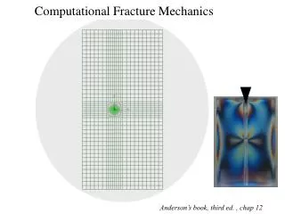
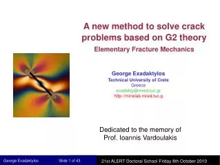
A new method to solve crack problems based on G2 theory Elementary Fracture Mechanics. George Exadaktylos Technical University of Crete Greece exadakty@mred.tuc.gr http://minelab.mred.tuc.g. Dedicated to the memory of Prof. Ioannis Vardoulakis. Historical notes.

E N D
A new method to solve crack problems based on G2 theory Elementary Fracture Mechanics George Exadaktylos Technical University of Crete Greece exadakty@mred.tuc.gr http://minelab.mred.tuc.g Dedicated to the memory of Prof. Ioannis Vardoulakis
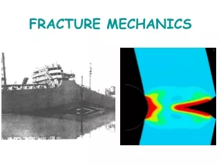
Historical notes The presence of crack-like voids is known to have a profound effect on the strength and mechanical properties of materials. Griffith (1921) first showed that the low tensile strength of glass could be explained by the presence of slit like cracks. Irwin (1957) extended Griffith's ideas by introducing the concept that a Critical Energy Release Rate (ERR) governs fracture, while Barrenblatt (1962) developed the concepts of modes I, II, and III crack tip Stress Intensity Factors (SIF’s) as governing extension, shearing, and tearing modes of deformation. Irwin (1957) showed the equivalence of the ERR and the crack tip SIF’s, and crack tip SIF’s for a wide variety of crack geometries have long before been compiled (e.g. Sih (1973)). Grittith A. A. The phenomenon of rupture and flow in solids. Phil. Trans. R. Soc. Lond, 221A, 163-198 (1921). Irwin G. R. Analysis of stresses and strains near the ends of a crack traversing a plate. J. Appl. Mech. 24, 361-364 (1957). Barrenblatt G. I. Mathematical theory of equilibrium cracks in brittle fracture. Advances in Applied Mechanics, Vol. 7. Academic Press, New York (1962). Sih G. C. Handbook of Stress Intensity Factors. Institute of Fracture and Solid Mechanics, Lehigh University, Bethlehem (1973).
Modes of fracture (Ch 1 CWS) Mode II and III cracks bear a certain analogy to edge and screw dislocations, respectively, in the sense that displacement discontinuities exist along the crack surface behind the crack tips. The superposition of the three basic modes is sufficient to describe the most general plane case of local crack tip stress and deformation fields.
Remarks: • The theoretical foundation of Fracture Mechanics may be soundly based • upon the Linear Small Strain Theory of Elasticity, regardless of the • phenomena occuring within the plastic zone at the crack tip which precipitates • fracture. • The failure criterion may be based upon a limiting intensity of the local elastic • stress field in the neighborhood of the crack tip. This limit may be specified in • terms of a single parameter. This parameter was initially recognized • historically to be the so called Strain Energy Release Rate (SERR) and was later • shown to be related to the SIF (fracture toughness). • The correct value of the SIF to be applied in design should be based upon • appropriate experimental data in combination with the appropriate theoretical • Stress analysis (the latter is also our topic for discussion!!). • Cracks are taken to be branch cuts i.e. lines or surfaces of displacement • discontinuity in 2D or 3D.
Stresses & displacements in cracked bodies (Ch 2 CWS) Step 1: Choose the following Westergaard function Step 2: Moving the origin to the crack tip Step 3: Expand f(ζ) in MacLaurin series (analytic):
State of affairs at the crack tip Plane strain solution:
Kinematics of mode III crack Westergaard Stress function Solution
Determination of Stress Intensity Factors (Ch 3 CWS) • Crack tip solutions using the Westergaard Stress Function • (Westergaard, 1936) Choose:
The value of constant C may be determined from the BC’s away from the crack and the resulting stresses must satisfy BC’s at the crack surface. At infinity: But the stresses
2a. Muskhelishvili’s approach using complex potential functions & conformal mapping The concept of complex SIF Consider the mapping function: For the right-hand crack tip
Example: Straight crack subjected to a concentrated force This problem is of particular interest as it may be used as a Green’s Influence Function to form the solution to other problems. where: corresponds to z=b
2b. Muskhelishvili’s approach using Cauchy type SIEs Another efficient method for solving plane elasticity crack problems and estimating the SIFs at crack tips is the method which reduces the problem to a Cauchy type singular integral equation by considering a curvilinear crack composed of a series of edge dislocations.
3. Finite element methods • Discretization techniques such as FEM are not basically well suited to problems containing singularities. In order to deal with this difficulty, two basic approaches have been developed: • a) Non-singular crack-tip models • b) Singular crack-tip elements • Non-Singular Models • By using a very high density of elements near the tips, SIFs were derived from near tip Eqs. for stresses or displacements (latter more accurate than the former)
Motivation It has been briefly shown that even though much achievement has been made in crack modeling techniques (analytical and numerical), a simple and practical crack modeling technique is still needed, in particular for complex multiple crack growth problems (in Structural Geology,Rock Mechanics, Structural Engineering, Petroleum Engineering, Biomechanics etc).
Constant normal and shear displacement discontinuities The Displacement Discontinuity (DD) method, as originally presented by Crouch [1976,1990], is based on a solution of the Neuber-Papkovitch displacement functions, which expresses the stresses and displacements at a point due to a Constant Displacement Discontinuity (CDD)(dislocation) over a finite line segment (i.e. a branch cut).
The uniformly pressurized crack problem Analytical solution: Assumption: line segments are small enough so that the DD along Oy-axis can be taken as constant over each segment Numerical approximation: Fundamental sol.: On each segment-j with a CDD along its entire length the stress is:
If this constant DD occurs at the j-th element of the crack then eq. (3) takes the form The stress at the midpoint of the i-th segment due to a DD at the j-th segment is found by setting , Unknown (?) Superposition: Influence coefficients for the special case of y=0 It is noteworthy that the central point used by Crouch in his DD element formulation represents the first Gauss-Chebyshev integration point.
BC’s of the uniformly pressurized crack problem CDD approximate solution Eq. (9) is an approximation of the following Singular Integral Equation of the 1st kind Hadamard finite-part integral
Overestimation of the relative displacements between the crack surfaces in the Crack tip region is a consequence of assuming that the normal stress at the mid-point of the i-th line segment represents the average stress over the segment.
Consider the extreme case in which the crack is modeled by one constant DD element of width 2 This solution for the opening of the crack may be compared with the exact solution . The numerical solution overestimates the maximum opening of the crack in this case by π/2
Ιn turn, overestimation of relative displacements of crack lips means overestimation of SIF’s!!!....see Eqs below Perspectives 1. Avoid more elaborate elements with more than one collocation points. 2. Simply you need a better measure of the average stress at each discontinuity location than the simple midpoint value used.
The impact of non-linearly varying local stress fields on the constitutive law for the stress For linearly varying fields: For quadratically varying fields: Field theories, which are based on averaging rules that include the effect of higher gradients, are called higher gradient theories. In particular above rule (B.5) represents a 2nd gradient rule, and can be readily generalized in 2D and 3D by introducing the Laplacian operator instead of the second derivative.
Simple G2 theory Prescribed profile of a Mode III crack Extra BC Fourier integral transform:
Solution of the single straight Mode III crack problem BC #1. BC #2. For c=0:
In the sequel we seek that value of the length scale that gives the exact agreement of the mid-point displacement of the uniformly pressurized CDD with the analytical solution for the uniformly pressurized crack,assuming that the latter is discretized with only one element. The above value of DD should be equal to the mid-point opening of the Mode-I crack as it given from Eq. (2) Solution!..
Construction of the new G2CDD element (G2 stands for grade-2 or 2nd gradient theory) Creation of new Influence Functions !!!.... New G2-term
Comparison of G2CDD with CDD & LDD: 1st case of Mode III crack problem under uniform shear
The case of three co-linear straight cracks Analytical solution:
Interaction of multiple cracks with a free surface This solution is constructed by superposition from the infinite body results presented in Part I by using the classical method of images (Hirth and Lothe, 1982).
Conclusions • A brief account of existing analytical methods for attacking LEFM problems has been made. • A new CDD element was presented for the numerical solution of Mode I, II and III crack problems, based on the strain gradient elasticity theory in its simplest possible Grade-2 (second gradient of strain or G2 theory) variant. • It has the advantage of simplicity, yet it has rather good accuracy appropriate for the fast solution of multiple crack problems.