Download
1 / 17
180 likes | 469 Views
Indianapolis. AIRCRAFT WIRE DEGRADATION STUDY 6 November 2002 Joe Kurek Nick Kirincich Multi-Disciplined Engineer Section Manager, Wiring Design (317) 306-7029 (317) 306-7264 kurekj@indy.raytheon.com kirincichn@indy.raytheon.com.

E N D
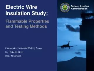
Indianapolis AIRCRAFT WIRE DEGRADATION STUDY 6 November 2002 Joe Kurek Nick Kirincich Multi-Disciplined Engineer Section Manager, Wiring Design (317) 306-7029 (317) 306-7264 kurekj@indy.raytheon.com kirincichn@indy.raytheon.com This work is being performed under contract to the FAA Technical Center (Contract No. DTFA03-02-C-00040)
Goal • To study the degradation mechanisms of five wire types commonly used for commercial airframe wiring, in order to understand and model the “aging” mechanisms. • WHY? To ensure safe long term operation of aircraft by fully understanding the reliability of electrical wire used in aircraft electrical interconnect systems.
Exposed to Heat / Humidity Exposed to Heat, Flex Wire Issues Other examples in previous presentation
Specific Goals • To attempt to develop algorithms in an effort to predict the degradation of wire in aircraft. • To determine degradation of wire relative to original performance specifications. • To establish relationships between performance degradation and potential failure modes, and to determine the critical thresholds. • To determine how thresholds can be used to eliminate or mitigate potential wiring hazards. • To identify major model perturbations.
Tasks • Phase I: Development of Test Program Aug 01 - May 02 • Phase II: Execution of Test Program Oct 02 - Aug 04 • Phase III: Analysis and Reporting Apr 04 - Dec 04
The Team • Direct Team • Raytheon Technical Services (lead) • Brookhaven National Laboratories • Sandia National Laboratories • Lectromechanical Design Company • Qualstat Services • Indirect Team
Phase I: Develop and Plan Study • Required Items for the study • Background study • Determine baseline data • Define Wire types to evaluate • Identify aging variables • Identify perturbations to the aging process • Develop a test plan • Develop a project plan • Develop a quality assurance plan • Draft test procedures • Define test protocols • Develop Statements of Work for subcontractors • Coordinate with industry stakeholders • Complete
Wire Types to Evaluate • Aromatic polyimide (PI) tape wrap (US & European versions) • Aromatic polyimide tape wrap with fluorocarbon bonding layers and polytetrafluoroethylene outer wrap (PI/PTFE) composite • Crosslinked aliphatic polyimide (XPI), extruded • Crosslinked modified ethylene tetrafluoroethylene (XLETFE), extruded • Polyvinyl chloride with extruded polyamide outer jacket (PVC/Nylon)
Variables that may Affect Wire Aging • Time • Thermal • Electrical • Mechanical • Bend, static • Bend, dynamic (Flex) • Abrasion, Vibration • Thermal Expansion • Chemical • Aircraft Fluids (cleaners, hydraulic fluid, lubricants, deicing fluids, etc.) • Humidity • Oxidizers (Ozone, NOx, SOx, etc.) • Radiation • Heat • Ultraviolet • Biological Organisms
Perturbations • Identify perturbations to the wire aging process • Uncontrollable Stressors that can include • wiring design • wiring installation or installation deficiencies • maintenance (EIS or aircraft) • operational extremes outside of the design guidelines • exposure to various debris outside of the design guidelines • exposure to high temperature caused by unpredicted environmental conditions • lightning • electrical shorts • component failure • Actual conditions any specific wire is exposed to during its life is unknown
Evaluation Tests • Tests that will be utilized • Some specific techniques currently used • Visual • IR/DWV • Tensile and Elongation • Flammability • Time Domain Reflectometry (TDR) • Some new techniques to evaluate • Terahertz • Insulation Modulus/Hardness • Inherent Viscosity • Weight Loss • Oxidation Induction Time • FTIR Spectroscopy • UV/VIS Spectroscopy
Test Method & Failure Criteria • Method based on the standard ASTM Method 3032 for wire. • “Accelerated Aging” type conditioning of wire specimens • Using test variables • Stressors (Flex, Thermal Shock, Vibration, Fluid Exposure) • Conditions (Temperature, Humidity, Static Bend) • Not all variables can be examined • Each wire type has unique test protocol • Cycle specimens through conditioning and testing until failure • Test specimens • Start with new wire • Test wire following periods of accelerated aging • Wire specimens fail when... • Insulation Resistance cannot be held • Wire cannot hold dielectric voltage • Conductor cannot pass current
Test Protocol Example • FIGURE 1: TEST PROTOCOL I – STRESSOR 1 & CONDITIONS A, A+, B, C, D, E, and J 1/
Phase II: Execution • Get subcontractors under contracts • Procure all required materials • Finalize test plan • Finalize test protocol • Finalize test procedures • Disposition comments to test plan • Finalize Schedule in a project plan • Execution of test program
Phase III: Analysis & Reporting • Full Data analysis • Draft Report • Lab Reports • Final Report • Request Industry Comments • Present to FAA • Scheduled to begin April 2004, and to complete December 2004
Anticipated Results • Baseline standard for conditioned wire samples. • Benchmark for correlation of novel aircraft wiring test techniques. • Method for evaluation for future wire studies. • Curves that represent the time to failure of the samples under specific environments. • Curves that correlate the change of the “state of wire” to data obtained from other techniques. • Thresholds that may be established to mitigate increased potential safety risks.
Possible Correlation of Data Log Time (t) 1/Temperature (K) • Modeling Degradation Times and Property Results • Model: Log Time = [ a + b * ( 1 / Temp ) + c * (# Cycles stressed ) ] Log time • f (Property) = model of similar form? linear, quadratic, etc. • Model developed for each combination of Dynamic Stressor Test and Aging Condition. Several models per wire type. • Will also compare life estimates (e.g. temperature indexes) versus the design variables & interactions