Download

1 / 45
450 likes | 464 Views
Jet Reconstruction in ATLAS. Peter Loch University of Arizona Tucson, Arizona, USA. e-mail: loch-at-physics.arizona.edu. Outline. Jets at LHC Brief overview on sources for jets and jet features at LHC Physics environment: Underlying Event and Pile-up Jet reconstruction in ATLAS

E N D
Jet Reconstruction in ATLAS Peter Loch University of Arizona Tucson, Arizona, USA e-mail: loch-at-physics.arizona.edu
Outline • Jets at LHC • Brief overview on sources for jets and jet features at LHC • Physics environment: Underlying Event and Pile-up • Jet reconstruction in ATLAS • Jet finders • Tower and cluster jets • Jet calibration strategies • In-situ calibration • More from jets at LHC • Jet reconstruction performance • Mass reconstruction and jet substructure analysis • Jet shapes • Summary & Outlook
W. Stirling, LHCC Workshop “Theory of LHC Processes” (1998) *annotation from J. Huston, Talk @ ATLAS Standard Model WG Meeting (Feb. 2004) Jets at LHC • New kinematic regime for jet physics • Jets can be much harder • Jets get more narrow in general (kinematic effect ~αs) • Higher energies to be contained in calorimeters • Jet reconstruction challenging • Physics requirements typically 1% jet energy scale uncertainty • top mass measurement in ttbar • LHC is a top factory! • hadronic final states in at the end of long decay chains in SUSY • Quality takes time • Previous experiments needed up to 10 years of data taking to go from ~4% down to ~1% • Can often not be achieved for all kinds of jets and in all physics environments
Jets from QCD Processes • Jets at low pT most likely produced by gluon fusion • Large phase space for radiation • Expectation are multi-jet final states even for 2→2 processes • More likely quark jets at higher pT • Less radiation (Sudakov suppression) • Less jets in events • Narrower jets (again) • Large kinematic range • pT range 10-5000 GeV/c • Di-jet mass reach several TeV/c2 • Multitude of jet flavours • Expect corresponding variety of jet shapes with possibly specific calibrations!
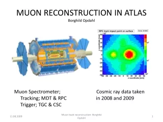
Physics Environments @ LHC • Underlying event • Refers to multiple interactions between the two colliding protons • Typically correlated with hard scatter • Increased activity compared to Tevatron • more phase space A.Moraes, HERA-LHC Workshop, DESY, March 2007 LHC prediction: x2.5 the activity measured at Tevatron! Number charged tracks in transverse region independent of luminosity →present at day 1 at LHC! CDF data (√s=1.8 TeV) CDF data: Phys.Rev, D, 65 (2002) Rick Field’s (CDF) view on di-jet events pT leading jet (GeV)
no pile-up added LHC design luminosity pile-up added Et ~ 81 GeV Et ~ 58 GeV Pile-up • Large pp total cross-section (~75mb) • ~23 “minimum bias” (soft to medium hard) collisions between protons in the same bunch in addition to triggered hard scatter • @ 1034 cm-2 s-1 • Poisson distributed • Similar dynamics as UE • Statistically independent • No correlation to hard scatter! • Generate lots of additional particles in addition to the underlying event • ~370 particles/unit rapidity per bunch crossing (3700 within ATLAS) • ~1,800 charged tracks in ATLAS/bunch crossing • High crossing rate at LHC (40 MHz) • Calorimeter signals typically to slow • Short signal shaping, bi-polar shaping function (ATLAS) • Long signal history (~500-600 ns) generates “out-of-time” pile-up • Canceling area → integrated effect 0 • Careful, only true in limit of continuous collisions • Can be treated as noise in calorimeter • Asymmetric! P. Savard et al., ATLAS-CAL-NO 084/1996 R = 0.7
Experimenter’s View on Jets longitudinal energy leakage detector signal inefficiencies (dead channels, HV…) pile-up noise from (off- and in-time) bunch crossings electronic noise calo signal definition (clustering, noise suppression ,…) dead material losses (front, cracks, transitions…) detector response characteristics (e/h ≠ 1) jet reconstruction algorithm efficiency jet reconstruction algorithm efficiency added tracks from in-time (same trigger) pile-up event added tracks from underlying event lost soft tracks due to magnetic field physics reaction of interest (interaction or parton level) We like to factorize the calibration and corrections dealing with these effects as much as possible!
collinear sensitivity (2) (signal split into two towers below threshold) infrared sensitivity (soft gluon radiation merges jets) collinear sensitivity (1) (sensitive to Et ordering of seeds) Theoretical Requirements for Jet Finders • Infrared safety • Absence of additional radiation splits jets • Presence of radiation merges jets • Collinear safety • Split seeds
Experimental Requirements for Jet Finders • Detector technology independence • Minimal contributions to spatial and energy resolution • Insignificant effects of detector environment • Noise • Dead material • Cracks • Easy to calibrate • Well… • Environment independence • Stability with changing luminosity • Identify all physically interesting jets from energetic partons in pertubative QCD (pQCD) • High reconstruction efficiency • Implementation • Fully specified • All selections and other configurations known • Efficient use of computing sources
Seeded cone Place cone with radius R around seed pT > 1 GeV Collect all particles in cone Re-calculate energy and direction of cone 4-momentum recombination Find more particle in new cone Stop until no more particles to be found Stable solution Particles can be shared between jets Is not infrared safe Needs split & merge (50% threshold) May miss signficant energy Dark jets Recursive recombination (kT) Calculate for all particles i and pairs ij : Combine any two pairs to jet if: Else remove i from list Is a jet Calculate new combinations Stop when all particles declared jets Each particle is part of one jet only (exclusive assignment) Infrared safe Popular Jet Algorithms in ATLAS
Jet Finders in ATLAS • Alternative applications: • CDF mid-point, Cambridge/Aachen recursive recombination (0th order kT), “optimal jet finder” (event shape fit) • More options: move to FastJet libraries • CMS, theory • No universal configuration or jet finder • Narrow jets • W->jj in ttbar, some SUSY • Wider jets • Inclusive jet cross-section, QCD mW N.Godbhane, JetRec June 2006 P.-A. Delsart, June 2006
Electromagnetic Calorimeters: • Liquid Argon/Pb accordion structure; • highly granular readout (~170,000 channels); • 0.0025 ≤ Δη ≤ 0.05, 0.025 ≤ Δφ ≤ 0.1; • 2-3 longitudinal samplings; • ~24-26 X0 deep • covers |η|<3.2, presampler up to |η|<1.8; Central Hadronic Calorimeters • Scintillator/Fe in tiled readout; • Δη x Δφ = 0.1 x 0.1 • 3 longitudinal samplings, • covers |η|<1.7; EndCap Hadronic Calorimeters • Liquid Argon/Cu parallel plate absorber structure; • Δη x Δφ = 0.1 x 0.1 (1.5<|η|<2.5), Δη x Δφ = 0.2 x 0.2 (2.5<|η|<3.2); • 4 samplings; Forward Calorimeters • Liquid Argon/Cu or W absorbers with tubular electrodes in non-projective geometry; • Δη x Δφ ≈ 0.2 x 0.2 (3.2<|η|<4.9) • 3 samplings; ATLAS Calorimeters Electromagnetic Liquid Argon Calorimeters Tile Calorimeters η=1.475 η=1.8 η=3.2 Forward Liquid Argon Calorimeters Hadronic Liquid Argon EndCap Calorimeters
ATLAS Calorimeter Details Cryostat walls (warm/cold) Electromagnetic Barrel Module Hadronic EndCap (2 wheels) to interaction vertex p from LHC Electromagnetic EndCap FCal1 FCal3 Cu Shielding FCal2 total ~200,000 channels, with hadronic coverage ~10 absorption lengths in full acceptance (|η|<5) and a typical level of non-compensation e/h≈1.3-1.6;
Calorimeter Signals: Towers • Imposes regular grid view on event • Δη×Δφ = 0.1×0.1 • Motivated by event ET flow • Natural for trigger! • Calorimeter cell signals are summed up in tower bins • No cell selection, all cells are included • Indiscriminatory signal sum includes cells without any true signal at all • Sum typically includes geometrical weight • Towers have fixed direction • Massless four-momentum representation projective cells non-projective cells
Electronic Noise in Calorimeter Cells Pile-up Noise in Calorimeter Cells S. Menke, ATLAS Physics Workshop 07/2005 S. Menke, ATLAS Physics Workshop 07/2005 Calorimeter Signals: Topological Clusters • Attempt to reconstruct particle showers • Establish local signal correlations in (neighbouring) cells • “energy blob” in 3-d • Growing volume algorithm using seeds and signal thresholds • Primary seeds start cluster • Secondary seeds among neighbours control growth • Basic cell selection threshold suppresses noise • All thresholds use signal-over-noise rather than signal • Signal significance is above a constant (but complex) threshold • Note: smallest reliably measurable energy is changing with noise! • Avoids regional energy thresholds (lots of tuning) • Uses experimentally accessible information • Gets the best out of the calorimeter!
Principle of Topological Clustering 1 1 1 Primary seeds 1 1 1 1 1 1 1 1 1 1 1 1 1 1 1 1 1 1 4 1 1 4 1 4 Secondary seeds 5 1 1 1 5 1 5 1 1 15 4 1 1 4 1 4 1 4 1 4 2 1 1 1 5 1 1 4 1 4 1 4 5 1 4 5 4 5 2 2 2 2 1 1 5 2 5 2 2 2 2 2 2 2 2 3 3 3 Basic threshold 2 2 2 2 2 2 2 3 3 3 3 2 2 2 2 2 3 3 3 3 3 3 3 Cluster splitting introduces geometrical weights!
Tower Jets in ATLAS • Sum up electromagnetic scale calorimeter cell signals into towers • Fixed grid of Δηx Δφ = 0.1 x 0.1 • Non-discriminatory, no cell suppression • Works well with pointing readout geometries • Larger cells split their signal between towers according to the overlap area fraction • Tower noise suppression • Some towers have net negative signals • Apply “nearest neighbour tower recombination” • Combine negative signal tower(s) with nearby positive signal towers until sum of signals > 0 • Remove towers with no nearby neighbours • Towers are “massless” pseudo-particles • Find jets • Note: towers have signal on electromagnetic energy scale • Calibrate jets • Retrieve calorimeter cell signals in jet • Apply signal weighting functions to these signals • Recalculate jet kinematics using these cell signals • Note: there are cells with negative signals! • Apply final corrections
Determination of Tower Jet Calibration • Sample of fully simulated QCD di-jet events from hard scatter pT>17 GeV/c to kinematic limit • Electronic noise included in simulation • Match reconstructed calorimeter jet with close-by particle jet • Both jets reconstructed with seeded cone R=0.7 • pTseed>1 GeV/c • Overlap threshold 50% • Match exclusive: only accepted if only one jet close by • Calorimeter jets are based on tower signals in a grid of ΔηxΔη= 0.1x0.1 • Access cell signals in jet • H1 motivated cell signal weighting strategy • Determine cell signal weights in resolution optimization fit using truth particle jet energy as normalization • Weights are function of cell location and cell signal density • Dense signals – em, less dense signals hadronic • Re-calculate jet four-momentum using cell weights • Jet energy and direction change
Kristin Lohwasser, September 2007 Tower Jet Performance • Signal linearity • Relative to matched MC truth jet! • Energy resolution • Relative to truth S. Padhi, ATLAS Physics Workshop 07/2005 S. Padhi, ATLAS Physics Workshop 07/2005
Signal linearity as function of jet direction Cracks less visible for wider jets, as expected No strong jet energy dependence Relative energy resolution as function of jet direction Cracks deteriorate signal Relative effect stronger dependend on jet energy, less on jet size Tower Jet Uniformity Kristin Lohwasser, September 2007 Kristin Lohwasser, September 2007
Cluster Jets in ATLAS • Attempt to factorize • Noise suppression • Noisy cells are removed • Hadronic calibration • Signal weighting in cluster context, no jet bias • Dead material corrections • Limited to vicinity of clusters • Cannot correct if no signal at all nearby • Out-of cluster corrections • Efficiency correction for clustering algorithm • Provides calibrated input to jet finding • Relative mis-calibration O(5%) • Instead of O(30%) • Clusters can be interpreted as massless pseudo-particles • ATLAS convention, see later!
Why Cluster Jets At All? • Reduce noise contribution • Fixed cone tower jet • Fixed cone cluster jet Iacopo Vivarelli, September 2006 Iacopo Vivarelli, September 2006
Determination of cluster calibration • Classification • Use measurable cluster variables to determine if cluster looks electromagnetic, hadronic, or noisy • Cluster location (“early”) and average cell signal density useful to classify electromagnetic and hadronic clusters • Noisy clusters are typically seeded by negative signal • Often negative total cluster energy • Hadronic weighting • Apply only to hadronic clusters • Uses cluster direction, cluster energy, cell signal density and cell location (sampling layer) to find cell signal weights • Dead material corrections • Apply to hadronic and electromagnetic clusters • Uses DM corrections parametrized as function of cluster shapes • Out of cluster corrections • Account for lost true signal due to clustering • All corrections are derived from single pions and photons • Detailed simulations are needed for most of them • Can all be benchmarked with test beam data! • Cannot correct for everything at cluster level • No signal, no correction!
Cluster Jet Signal Linearity • Flat response in Et and rapidity • Forward region problems under study • Missing ~8% jet energy • ~3% cluster mis-classification • Cluster classified as em, but really is hadronic • ~3% signal efficiency • Signal of low energetic particles below cluster threshold • ~2% electromagnetic calibration • Em clusters need own calibration • Basic scale insufficient • Remember: calibration so far comes from single particle! • No jet context whatsoever! • Studies under way… • We are now looking at topology based on clusters • Also started to look at jets S.Menke/G. Pospelov March 2007 T&P S.Menke/G. Pospelov March 2007 T&P
Use of kinematic constraints in pp Photon/Z+jet pT balance Central value model dependent! Topology Hard cuts on back-to-back no problem at LHC! Kinematic limit ~400 GeV/c pT(photon) for 1% First shot at jet energy scale! W mass Powerful but very special jets W color-disconnected Narrow jets Di-jet balance Extrapolation tool to high pT Also detector uniformity Topology dependence Normalization strategy Match reconstructed pT balance with particle level balance Unfold topology dependences Jet Energy Scale Corrections Sigrid Jorgensen, September 2006
Photon+Jet • Missing Et Projection Fraction (MPF) • Pioneered by DØ • Low sensitivity to pile-up • No jet context needed • Can use clusters, towers, even cell signals Doug Schouten, ATL-COM-PHYS-2007-057,September 2007 uncalibrated clusters
η(W) ~1.8 P. Savard, P. Loch, CALOR97 Jet Energy Scale From W • Challenge: pile-up and W boost • Pile-up can “improve” jet energy scale! • W colour-disconnected from rest of event • Cannot expect the same particle flow around jet • Not straight forward to carry over corrections based on W mass to other jets at 1% level
Very High pT Jets • Reconstruction concern: leakage • Find indicators in jet signal to tag leakage • Late showering in calorimeter • Use muon spectrometer hits behind jet • No energy measurement, but good tag • Studies underway to validate jet energy scale at very high pT • pT balance in systems with very high pT jet balancing several lower energetic jets Frank Paige, ATLAS T&P Week February 2006
Efficiency Only free parameter: matching radius Rm No kinematics matching! Purity Relates to fake rate Jets in VBF! Jets in VBF! Martin Schmitz, September 2007 Martin Schmitz, September 2007 Jet Finder Efficiencies in ATLAS
Pile-Up in Clone Cluster Jets • Expect cluster to suppress noise • Works for pile-up as well • Flucutations can be suppressed if correct noise RMS used in cluster finder • Cluster noise cuts are symmetric! • Some energy offset observed • Pile-up is asymmetric • Baseline larger for correct RMS • Bias toward positive signals by noise selection Doug Schouten, ATL-COM-PHYS-2007-057,September 2007 Et Pile-up in R=0.2 cone Doug Schouten, ATL-COM-PHYS-2007-057,September 2007
Gained interest at LHC Heavily boosted top decays All decay products reconstructed in one jet Jet mass one observable indicating top decay Jet substructure also sensitive to source! Mass measurement challenging Particle jet level mass is reference Simulations only! Mass of calorimeter jet is affected by shower spreads Enters: signal definition dependence, cluster shapes, noise,… No significant attempt at Tevatron or elsewhere cluster jets tower jets cluster jets tower jets PL & Chiara Paleari, Poster @ SLAC ATLAS Workshop, August 2007 cluster jets tower jets relative mass difference Jet Masses
Mass Reconstruction Sensitivities • Contribution from low energetic particles lost • Dead material and magnetic field • Overall effect depends on signal definition • How about effect on mass? • Exercise: remove particles below pT threshold from jet and re-calculate mass • Remember: towers are not calibrated • More severe effect of cut in tower jets • Clusters are calibrated • More similar to particle selection in jets
change of mass QCD kT jets, D = 0.6 log10(least biased reconstructed mass/GeV) Mass Sensitivity
Jet Substructure • Mass too complex? • Can be too sensitive to small signals in jets • UE, pile-up, other noise • Use YSplitter to detect substructure • Determines scale y for splitting a giving jet into 2,3,… subjects, as determined by ycut, from • More stable as only significant constituents are used ? • At least additional information to mass • Other option: • Look at mass of 2…n hardest constituents (Ben Lillie,ANL) J. Butterworth et. al,, ATL-COM-PHYS-2007-077,October 2007 Not very sensitive to calorimeter signal details!
Jet Shapes (1) • 1st question: any relation between number of particles, towers, clusters in jets? • Most interesting for kT • D = 0.6 here • Look at matching callorimeter/truth jets • Note: not the most important variable! • We already expect change of “jet picture” by detector signal definition • Hints on resolution power for jet shape variables and mass
Jet Shapes (2) • We expected clusters to represent indivdual particles • Cannot be perfect in busy jet environment! • Shower overlap in finite calorimeter granularity • Some resolution power, though • Much better than for tower jets! • ~1.6:1 particles:clusters in central region • ~1:1 in endcap region • Best match of readout granularity, shower size and jet particle energy flow • Happy coincidence, not a design feature of the ATLAS calorimeter!
cluster jets tower jets hadron jets PL & Chiara Paleari, Poster @ SLAC ATLAS Workshop, August 2007 Fraction of energy outside cone around jet axis (Rcone=0.3) log10(pTjet/GeV) Jet Shapes (3) • Jet density • Calculate energy outside of cone R = 0.3 as function of pT and direction • Classic Tevatron measurement • Experimental indication of transition from (low pT) gluon to (high pT) quark jets • Example: kT jets in QCD • D = 0.6
Summary • General • Everything you have seen here from ATLAS is based on simulations and thus very preliminary • Real data can bring us surprises (good and bad) • Jet signals • Cluster signal (~200/event) good basis for jet finding in physics analysis context • Final jet energy scale corrections depend on analysis choices for jet finders, -configurations, selected event topologies… • What we can get from jets • Strong interest to go beyond Tevatron jets • Jet masses and substructure analysis of great interest for boosted heavy particle decays • Jet shapes can test basic jet formation dynamics ?? • New dimension added: jet signal shapes in calorimeters can improve calibration jet by jet
Outlook • Refined jet calibration • Use calorimeter jet signal shapes • We used cluster shapes already, now look at cluster distribution in jet • Use inner detector tracks • Large momentum fraction of jet in tracks indicates a very hadronic jet, i.e. more corrections • Jet origins • Use inner detector tracks and vertices to separate jets from hard scattering from jets from UE and/or pile-up (A. Schwartzman) • All this has not been used much in the past, but we have to address a 1% systematic error requirement somehow! • We are more than ready for data!
Jet Energy Scale (JES) • JES error very quickly systematically dominated • Large statistics in unexplored kinematic range already at low luminosity • Calibration channels quickly accessible • pT balance • Photon + jet(s) • Z+jet(s) later • Mass spectroscopy • W->jj in ttbar Dominant direct photon production gives access to gluon structure at high x (~0.0001-0.2) (precision ?)
Strong Coupling just from cross-section, can be improved by 3/2 jet ratio, but no competition for LEP/HERA! test of QCD at very small scale ( ) Compositeness PDFs di-jet cross section and properties (Et,η1,η2) constrain parton distribution function Deviation from SM Measurements with Jets sensitivity to compositeness scale Λ up to 40 TeV @ 300 fb-1 (all quarks are composites)
“H1” Style Cell Signal Weighting in ATLAS • Fit constraint: • Jet four-momentum calculation after fit • Final corrections for residual signal non-linearities • Algorithm dependencies • Available for seeded cone R=0.4, kT D=0.4, D=0.6 • Signal dependencies (cluster/tower) “massless pseudo-particles”