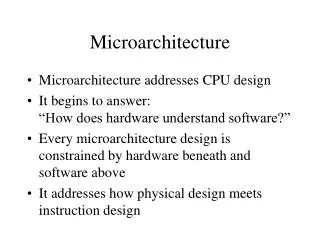
Hyper-Threading Technology Architecture and Microarchitecture
Hyper-Threading Technology Architecture and Microarchitecture. MASS Lab. Kim Ik Hyun. Outline. INTRODUCTION BACKGROUNDS HYPER-THREADING TECHNOLOGY ARCHITECTURE INTEL XEON PROCESSOR FRONT END OUT-OF-ORDER-EXECUTION ENGINE ETC Performance Evaluation Conclusions. BACKGROUNDS.

Hyper-Threading Technology Architecture and Microarchitecture
E N D
Presentation Transcript
Hyper-Threading Technology Architecture and Microarchitecture MASS Lab. Kim Ik Hyun.
Outline • INTRODUCTION • BACKGROUNDS • HYPER-THREADING TECHNOLOGY ARCHITECTURE • INTEL XEON PROCESSOR • FRONT END • OUT-OF-ORDER-EXECUTION ENGINE • ETC • Performance Evaluation • Conclusions
BACKGROUNDS • The amazing growth of the Internet and telecommunications is powered by ever-faster systems demanding increasingly higher levels of processor performance. • Microarchitecture techniques used to achieve past processor performance improvement have made microprocessors increasingly more complex, have more transistors, and consume more power • But, transistor counts and power are increasing at rates greater than processor performance.
BACKGROUNDS • Single-stream performance vs. cost
HYPER-THREADING TECHNOLOGY ARCHITECTURE • Hyper-Threading Technology makes a single physical processor appear as multiple logical processors. • To do this, there is one copy of the architecture state for each logical processor • the logical processors share a single set of physical execution resources. • instructions from logical processors will persist and execute simultaneously on shared execution resources
HYPER-THREADING TECHNOLOGY ARCHITECTURE • Processors without Hyper-Threading Tech • Processors with Hyper-Threading Tech
INTEL XEON PROCESSOR • Goal • One goal was to minimize the die area cost of implementing Hyper-Threading Technology. • A second goal was to ensure that when one logical processor is stalled the other logical processor could continue to make forward progress. • A third goal was to allow a processor running only one active software thread to run at the same speed on a processor with Hyper-Threading Technology as on a processor without this capability.
INTEL XEON PROCESSOR • Intel Xeon processor pipeline
FRONT END • The front end of the pipeline is responsible for delivering instructions to the later pipe stages. • Execution Trace Cache(TC) • Microcoded ROM • ITLB • Instruction decode logic • Uop Queue
Trace Cache • Trace Cache (TC) is the primary or Level 1 (L1) instruction cache. • Most instructions in a program are fetched and executed from the TC. • TC stores decoded instructions, called microoperations or “uops.” • Two sets of next-instruction-pointers independently track the progress of the two software threads executing. • TC is 8-way set associative, and entries are replaced based on a LRU algorithm
Microcode ROM • When a complex instruction is encountered, the TC sends a microcode-instruction pointer to the Microcode ROM. • The Microcode ROM controller then fetches the uops needed and returns control to the TC. • Two microcode instruction pointers are used to control the flows independently if both logical processors are executing complex IA-32 instructions • Both logical processors share the Microcode ROM entries.
ITLB • If there is a TC miss, then instruction bytes need to be fetched from the L2 cache and decoded into uops to be placed in the TC. • The Instruction Translation Lookaside Buffer (ITLB) receives the request from the TC to deliver new instructions • A request is sent to the L2 cache, and instruction bytes are returned. • These bytes are placed into streaming buffers, which hold the bytes until they can be decoded.
ITLB • Trace Cache Hit • Trace Cache miss
ITLB • ITLBs are duplicated. Each logical processor has its own ITLB and its own set of instruction pointers to track the progress of instruction fetch for the two logical processors. • Each logical processor has its own set of two 64-byte streaming buffers to hold instruction bytes in preparation for the instruction decode stage. • ITLBs and the streaming buffers are small structures, so the die size cost of duplicating these structures is very low.
Instruction decode logic • Decoding is only needed for instructions that miss the TC. • Decode logic takes instruction bytes from the streaming buffers and decodes them into uops. • Decode logic has to keep two copies of all the state needed to decode IA-32 instructions for the two logical processors even though it only decodes instructions for one logical processor at a time. • The decoded instructions are written into the TC and forwarded to the uop queue.
Uop Queue • After uops are fetched from the trace cache or the Microcode ROM, or forwarded from the instruction decode logic, they are placed in a “uop queue.” • This queue decouples the Front End from the Out-of-order Execution Engine in the pipeline flow. • The uop queue is partitioned such that each logical processor has half the entries. • This partitioning allows both logical processors to make independent forward progress regardless of front-end stalls (e.g., TC miss) or execution stalls.
OUT-OF-ORDER EXECUTION ENGINE • Out-of-order execution engine detailed pipeline
Allocator • The allocator logic takes uops from the uop queue and allocates many of the key machine buffers needed to execute each uop • 126 re-order buffer entries, 128 integer and 128 floating-point physical registers, 48 load and 24 store buffer entries. • If there are uops for both logical processors in the uop queue, the allocator will alternate selecting uops from the logical processors every clock cycle to assign resources.
Allocator • If a logical processor has used its limit of a needed resource, such as store buffer entries, the allocator will signal “stall” for that logical processor and continue to assign resources for the other logical processor. • By limiting the maximum resource usage of key buffers, the machine helps enforce fairness and prevents deadlocks. • if the uop queue only contains uops for one logical processor, the allocator will try to assign resources for that logical processor every cycle to optimize allocation bandwidth, though the resource limits would still be enforced.
Register Rename • The register rename logic renames the architectural IA-32 registers onto the machine’s physical registers. • The renaming logic uses a Register Alias Table (RAT) to track the latest version of each architectural register to tell the next instruction(s) where to get its input operands. • there are two RATs, one for each logical processor. • The register renaming process is done in parallel to the allocator logic described above
Instruction scheduling • Five uop schedulers are used to schedule different types of uops for the various execution units. • The schedulers determine when uops are ready to execute based on the readiness of their dependent input register operands and the availability of the execution unit resources. • The memory instruction queue and general instruction queues send uops to the five scheduler queues as fast as they can • The schedulers are effectively oblivious to logical processor distinctions.
Execution Units and Re-order buffer • The execution core and memory hierarchy are also largely oblivious to logical processors. • uops merely access the physical register file to get their destinations, and they write results back to the physical register file. • After execution, the uops are placed in the re-order buffer. • The re-order buffer decouples the execution stage from the retirement stage
Retirement • Retirement logic will retire uops for one logical processor, then the other, alternating back and forth. • If one logical processor is not ready to retire any uops then all retirement bandwidth is dedicated to the other logical processor. • Once stores have retired, the store data needs to be written into the level-one data cache.
BUS • The bus logic includes the local APIC interrupt controller, as well as off-chip system memory and I/O space. • requests from the logical processors are treated on a first-come basis • inherit the logical processor ID of the request that generated the transaction.
Single task and Multi task modes • Resource allocations
Performance Evaluation • On OLTP workload
Performance Evaluation • Web server benchmark performance
Performance Evaluation • More evaluation • www.intel.com/procs/perf/limits.htm
Conclusions • 3 goals are satisfied. • Showed performance gains of up to 30 % on common server application • Potential for Hyper-Threading Technology is tremendous.