PCM
PCM. Professor: Dr. Miguel Alonso Jr. Outline. Sample and Hold, and Sampling Frequency Quantization Dynamic Range and SNR Calculations Amplitude Companding D to A and A to D. Introduction. Concerned with the transfer of information in digital form Advantages: Noise Performance


PCM
E N D
Presentation Transcript
PCM Professor: Dr. Miguel Alonso Jr.
Outline • Sample and Hold, and Sampling Frequency • Quantization • Dynamic Range and SNR Calculations • Amplitude Companding • D to A and A to D
Introduction • Concerned with the transfer of information in digital form • Advantages: • Noise Performance • Ability to process signal at the source and destination DSP • PCM is the most common technique used today in Digital Communications for representing an analog signal by a digital word. • PCM is a technique for converting analog signals into a digital representation
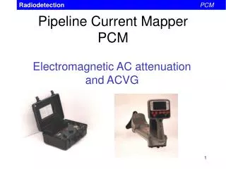
Sample and Hold, and Sampling Frequency • The first step is to sample and hold the analog input • PAM: • Natural, not good for sampling • Flat-top PAM • Sampling frequency must meet the Nyquist Criteria because of Aliasing • Fs ≥ 2*Fmax
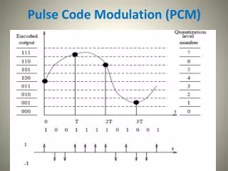
Quantization • Once the signal has been sampled, the binary conversion process can begin • In PCM systems, the sampled signal is segmented into different voltage levels, with each level corresponding to a different binary number. • This process is called quantization • Converted to the closest binary value provided in the digitizing system • At each sampling interval, the analog amplitude is quantized into the closest available quantization level
Resolution • q = Vmax / 2n • Quantization error or Noise results when the analog signal being sampled lies in between two quantization levels • Example: • 3 volt 40Hz Sine wave sampled in a 4-bit PCM system • Fs = ? • Q=?, Fclock = ?
Dynamic Range and SNR calculations • Dynamic range for a PCM system is defined as the ration of the maximum input or output voltage level to the smallest voltage level that can be quantized and/or reproduced by the converters • Vfs/q • DR = Vmax/Vmin = 2n • DRdB = 20*log10 Vmax/Vmin • DRdB = 20*log10 2n
SNRdB for a PCM system • SNRdB = 1.76 + 6.02*n • Signal to quantization noise • SNRq(dB) = 10log 3*(2n)2 • Example: A digitizing system specifies 55dB of dynamic range. How many bits are required to satisfy the DR spec? What is the SNRdB ? What is SNRq(dB) ?