Download
1 / 27
270 likes | 283 Views
Highlighting a potential problem with the existing Secure-LTF sequence design leading to dynamic range complications and proposing a solution to mitigate unintentional beamforming issues.

E N D
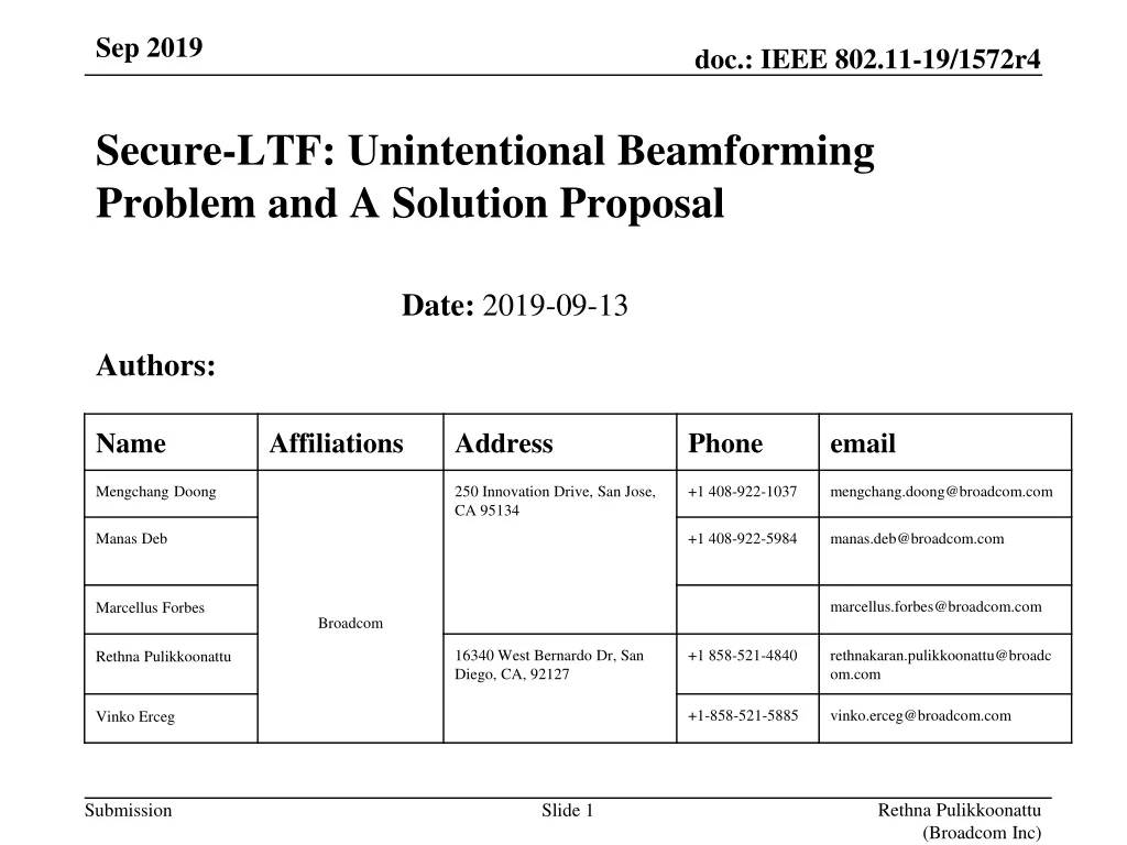
Secure-LTF: Unintentional Beamforming Problem and A Solution Proposal Date: 2019-09-1317-12-14 Authors: Rethna Pulikkoonattu (Broadcom Inc)
Abstract • This document highlights a potential problem with the existing design of secure LTF sequence. In its present form, while in multi stream scenario, unintentional Beamforming (constructive and destructive addition of signals) could take place during the secure LTF transmission portion, which leads to dynamic range complications at the receiver. We propose a possible solution to mitigate the problem. Rethna Pulikkoonattu (Broadcom Inc)
Secure-LTF Generation (from .11az/D1.0) • Additional notes from .11az/D1.0 • No single stream pilot subcarriers in the secure HE-LTFs, all subcarriers are mapped using the full P-HE-LTF matrix. • No CSD is applied to the space-time streams. • No spatial mapping, the Q matrix is a block identity matrix. • P ={7, 8, 9, 10} for {20, 40, 80,160/80+80} MHz PHY BW. P bits tCS PHE_LTF Matrix Mapping CSD Value Generator Frame Format Construction IDFT Zero-GI and Windowing IDFT Zero-GI and Windowing 3P+3 bits CSD Subcarrier Mapper 8PSK Sequence Generator … Randomized LTF Sequence 2P 8PSK symbols IDFT Zero-GI and Windowing Rethna Pulikkoonattu (Broadcom Inc)
Secure-LTF (Present Design): N_STS=2 and LTF_REP = 2 … HE-STF Seq1 - Seq2 Seq3 - Seq4 TX Stream 1 … HE-STF Seq1 Seq2 Seq3 Seq4 TX Stream 2 • The waveforms on TX stream 1 and stream 2 are perfectly aligned (in time domain, either in-phase or 180 degrees out of phase), causing unintentional beamforming, by way of constructive/destructive addition of signal. • Seq1, Seq2, Seq3 and Seq4 are generated from 4 different sets of 4P+3 bits. Rethna Pulikkoonattu (Broadcom Inc)
Secure-LTF (Existing Design): N_STS=2 and LTF_REP = 2 … HE-STF Seq1 - Seq2 Seq3 - Seq4 TX Stream 1 … HE-STF Seq1 Seq2 Seq3 Seq4 TX Stream 2 3dB average power increase. 9.6us RX RSSI 3dB Destructive interference Constructive interference Zero GI In case of in-phase LOS or some flat-fading cases (small indoor environment) RX signal energy stays low for 9.6us, which may cause RX packet abortion. Rethna Pulikkoonattu (Broadcom Inc)
Existing LTF: RX Waveform (Simulation) chan_indx = 2 • Simulation with TGnB Channel model • If no per-STS CSD is applied, unintentional beamforming can take place, resulting in a higher signal amplitude fluctuation in the time domain. This behavior will eat up the dynamic range of receiver circuitry PE HE-LTF1 HE-LTF2 HE-STF L-STF L-LTF L-SIG RL-SIG HE-SIG AGC in work Larger-than-usual signal amplitude caused by un-intentional beamforming (constructive interference). Smaller-than-usual signal amplitude caused by un-intentional beamforming (destructive interference). Rethna Pulikkoonattu (Broadcom Inc)
Potential Problems • Circuit dynamic range • The secure-LTF signal power at the receiver may end up boosted by up to 10*log10(N_STS) dB. Similarly, part of the LTF signal could be completely nulled out due to the destructive addition. • N_STS=2, can result in 3dB boost or a nulling. Can happen ~10% of time. • RX power can increase by up to 9 dB (for 8 TX stream case) when coherent interference happens. Extra circuit dynamic range will be required to accommodate such excessive power swing. • Regulatory concerns • Abrupt increase in power is a concern in some regulator domain • SNR loss due to Channel Estimation • Up to 1.2494 dB (=3-1.761 dB) (Theoretical max loss) Rethna Pulikkoonattu (Broadcom Inc)
Secure LTF design Proposal: Illustration for N_STS=2 and LTF_REP = 2 A1, A2, A3 and A4 are different secure-LTF sequences, which can be generated by the procedure described in .11az. With the following rule, the complexity increment for channel estimation is kept minimum compared to existing design in .11az. Matrix inversion is not necessary!! Only need extra phase rotations on H12 and H22 after the typical channel estimation procedure. The (time-domain) waveforms on TX stream 1 and TX stream 2, will look totally different. Improve randomness and thus the overall security The unintentional beamforminggets resolved Rule: Sequence A1, A2 are generated from 2 different (and independent) sets of 4P+3 bits. They are polyphaseGolay codes. The 8PSK sequence of A3 are generated from another independent set of 3P+3 bits. The az_csd of A3 is the same as A1. The 8PSK sequence of A4 is generated from 3P+3 bits which are a simple function of the previous 3 sets of 3P+3 bits. The az_csd of A4 is the same as A2. The function to generate 3P+3 bits for A4 is described in the subsequent pages. TX Stream 1 A1 - A2 B1 - B2 TX Stream 2 A3 A4 B3 B4 Rethna Pulikkoonattu (Broadcom Inc)
Proposed Design: RX Waveform (Simulation) With this proposal, the unintentional beamforming behavior is minimized. RX signal power stays even. PE HE-LTF1 HE-LTF2 HE-STF L-STF L-LTF L-SIG RL-SIG HE-SIG AGC in work Rethna Pulikkoonattu (Broadcom Inc)
LTF generation : Recap of the 4P+3 bits and the iterative process The 4P+3 bits can be divided into groups as shown below: These P bits are used to generate the az_csd. These 3P+3 = 3(P+1) bits are used to generate the 8PSK secured sequence. bP+3, bP+4, bP+5, b0, b1, … bP-1, bP, bP+1, bP+2, bP+6, bP+7, bP+8, bP+9, bP+10, bP+11, … b4P, b4P+1, b4P+2 s1(0) = exp(jq1) s2(0) = exp(jq2) jP-1= exp(jfP-1) j1= exp(jf1) j2= exp(jf2) … secure az_csd Initial values The iterative process A sequence of 2P 8PSK symbols are generated by P-1 iterations. Rethna Pulikkoonattu (Broadcom Inc)
“The Rule” and notations b0, b1, … bP-1, bP, bP+1, bP+2, … b4P, b4P+1, b4P+2 bP+3, bP+4, bP+5, bP+6, bP+7, bP+8, bP+9, bP+10, bP+11, jP-1= exp(jfP-1) j1= exp(jf1) j2= exp(jf2) s1(0) = exp(jq1) s2(0) = exp(jq2) secured az_csd tCS … … q2_A1 f1_A1 f2_A1 fP-1_A1 q1_A1 For A1 tCS_A1 … For A2 q2_A2 f1_A2 f2_A2 fP-1_A2 q1_A2 tCS_A2 … For A3 q2_A3 f1_A3 f2_A3 fP-1_A3 q1_A3 tCS_A3=tCS_A1 q1_A4 = -q1_A1 + q1_A2 + q1_A3 q2_A4 = -q2_A1 + q2_A2 + q2_A3 f1_A4 = -f1_A1 + f1_A2 + f1_A3 f2_A4 = -f2_A1 + f2_A2 + f2_A3 For A4 tCS_A4=tCS_A2 … fP-1_A4 = -fP-1_A1 + fP-1_A2 + fP-1_A3 We will explain why we choose this “-++” rule in the following pages. Rethna Pulikkoonattu (Broadcom Inc)
Notations and Equations to represent the function The 4P+3 bits for A1,A2, A3 and A4 are denoted by For A1: b1i for i=0,…4P+2. Secure bits required: 4P+3 For A2: b2i for i=0,…4P+2. Secure bits required: 4P+3. For A3: b3i for i=0,…4P+2. Secure bits required: 3P+3. For A4: b4i for i=0,…4P+2. Secure bits required: 0. b3i= b1i for i=0,…P-1 same az_csd for A1 and A3 b4i= b2i for i=0,…P-1 same az_csd for A2 and A4 For A4 s1(0) For A4 s2(0) For A4 jp for p=1,…,P-1 Rethna Pulikkoonattu (Broadcom Inc)
The iterative process Note: -jp= - exp(jfp) = exp( j(fp+p) ) s1(0) = exp(jq1) s2(0) = exp(jq2) s1(1) = [ exp( jq1 ) , exp( jq2 ) ] s2(1) = [ exp( j(q1+f1) ) , exp( j(q2+f1+p) ) ] initialization Iteration 1 Iteration 2 … Iteration 3 … Rethna Pulikkoonattu (Broadcom Inc)
For A4 (using iteration 2 as an illustration) initialization Iteration 1 Iteration 2 Re-notation Apply similar notation for A1, A2 and A3 Using the rule mentioned earlier, it can be rewritten as Phase addition is equivalent to value multiplication. Phase subtraction is equivalent to value division. “.*” and “./” denote point-wise multiplication and division for each element in the array. In our case, it means frequency domain point-wise operation. This relationship holds for all iterations. The final sequence A4 = A2 .* A3 ./ A1 We have just proven that the A4=A2.*A3./A1 is constructed with the same structure as A1, A2 and A3, and is therefore a PolyphaseGolaysequence with the same PAPR as others. Rethna Pulikkoonattu (Broadcom Inc)
Illustration for Channel Estimation A1 - A2 B1 - B2 TX Stream 1 A3= A1.*(A3./A1) A4= A2.*(A3./A1) B3= B1.*(B3./B1) B4= B2.*(B3./B1) TX Stream 2 Since this term is a fixed value within one repetition period, it can be viewed as part of the channel response. Since (A3./A1) is known, we can compensate for it after “typical” channel estimation block. [A1, A2 ] RX TX [A1, -A2 ] “Typical” Channel Estimation h11 TX stream 1 Est{ h11 } h12 Est{ h12 } .*(A1./A3) Est{ h21 } h21 [A1, A2 ] [A3, A4 ] .*(A3./A1) Est{ h22 } .*(A1./A3) TX stream 2 h22 Since A1 and A3 are 8PSK sequences, “.*(A3./A1)” and “.*(A1./A3)” are just phase rotations. Rethna Pulikkoonattu (Broadcom Inc)
Extension to larger spatial streams (e.g., N_STS=4 ) Easily scalable to arbitrary number of spatial streams Needs ( 2 * NHE_LTF - 1 ) additional secured sequences required A1 - A2 A3 A4 TX Stream 1 A5 A2.*A5./A1 -A3.*A5./A1 A4.*A5./A1 TX Stream 2 A6 A2.*A6./A1 A3.*A6./A1 -A4.*A6./A1 TX Stream 3 -A7 A2.*A7./A1 A3.*A7./A1 A4.*A7./A1 TX Stream 4 Rethna Pulikkoonattu (Broadcom Inc)
Matrix constructed in this manner is always invertible • It is a Hadamard matrix scaled by diagonal matrices. • Sequence properties (e.g., orthogonality, PAPR etc., ) are retained • NHE_LTF= 2 • NHE_LTF = 4 Rethna Pulikkoonattu (Broadcom Inc)
Matrix constructed in this manner is always invertible NHE_LTF = 6 (Orthogonal:Vandemonde, Signature, diagonal matrices) where Rethna Pulikkoonattu (Broadcom Inc)
Matrix constructed in this manner is always invertible NHE_LTF = 8 Rethna Pulikkoonattu (Broadcom Inc)
Conclusion • MIMO mode needs modification in Secure LTF design • Simple, scalable scheme exist to address the problem. One scheme is presented here. • Very minimal change in the receiver (channel estimation) • A byproduct of this design is that, it also helps to make the system more secure. Rethna Pulikkoonattu (Broadcom Inc)
Appendix Rethna Pulikkoonattu (Broadcom Inc)
NHE_LTF = 4 Matrix constructed in this manner is always invertible NHE_LTF = 2 Rethna Pulikkoonattu (Broadcom Inc)
Matrix constructed in this manner is always invertible NHE_LTF = 6 where Rethna Pulikkoonattu (Broadcom Inc)
Matrix constructed in this manner is always invertible NHE_LTF = 8 Rethna Pulikkoonattu (Broadcom Inc)
Math for Channel Estimation (using 2x2 as an example) Assume the frequency domain value of the kth tone for sequence A1, A2 and A3 are A1k, A2k and A3k respectively. Since A1k and A3k are 8PSK symbols, A1k and A3k can be written as exp( j * qA1k) and exp( j * qA3k) respectively. The k_th tone being send out through the two antennas: Symbol: n n+1 n+2 n+3 TX Ant 0: A1k -A2k B1k -B2k TX Ant 1: A3k A2k*exp( j*qA3k)*exp( -j*qA1k) B3k B2k*exp( j*qB3k)*exp( -j*qB1k) We can rewrite them as (only show symbol n and n+1) Symbol: n n+1 TX Ant 0: A1k -A2k TX Ant 1: A1k*exp( j*qA3k)*exp( -j*qA1k) A2k*exp( j*qA3k)*exp( -j*qA1k) Rethna Pulikkoonattu (Broadcom Inc)
Math for Channel Estimation (using 2x2 as an example) If the channel matrix for kth tone is Hk=[ h11_k h12_k ; h21_k h22_k ], then at the receiver for symbol n and n+1, we get (ignoring noise): RX Ant 0: y1[n] = h11_k* A1k + h12_k* A1k*exp( j*qA3k)*exp( -j*qA1k) y1[n+1] = h11_k* (-A2k )+ h12_k* A2k*exp( j*qA3k)*exp( -j*qA1k) RX Ant 1: y2[n] = h21_k* A1k + h22_k* A1k*exp( j*qA3k)*exp( -j*qA1k) y2[n+1] = h21_k* (-A2k )+ h22_k* A2k*exp( j*qA3k)*exp( -j*qA1k) We can write H12_k’ = h12_k*exp( j*qA3k)*exp( -j*qA1k) H22_k’ = h22_k*exp( j*qA3k)*exp( -j*qA1k) Substituting these into the equations, we get RX Ant 0: y1[n] = h11_k* A1k + h12_k’ * A1k y1[n+1] = h11_k* (-A2k )+ h12_k’ * A2k RX Ant 1: y2[n] = h21_k* A1k + h22_k’ * A1k y2[n+1] = h21_k* (-A2k )+ h22_k’ * A2k Rethna Pulikkoonattu (Broadcom Inc)
Math for Channel Estimation (using 2x2 as an example) Now we can solve h11 , h12’ , h21 and h22’ from previous equations RX Ant 0: y1[n] / A1k = h11_k + h12_k’ y1[n+1] / A2k = h11_k + h12_k’ RX Ant 1: y2[n] / A1k = h21_k + h22_k’ y2[n+1] / A2k = h21_k + h22_k’ By adding and subtracting the equations RX Ant 0 h11_k = ( y1[n] / A1k - y1[n+1] / A2k ) /2 h12_k’ = ( y1[n] / A1k + y1[n+1] / A2k ) /2 RX Ant 1 h21_k = ( y2[n] / A2k - y2[n+1] / A2k ) /2 h22_k’ = ( y2[n] / A2k + y2[n+1] / A2k ) /2 After we solve h12_k’ and h22_k’ , we can then compensate for the phase shift and get h12_k and h22_k h12_k = h12_k’ * exp( -j * qA3k) * exp( j * qA1k) h22_k = h22_k’ * exp( -j * qA3k) * exp( j * qA1k) Rethna Pulikkoonattu (Broadcom Inc)