Metal Machining
Metal Machining. Objectives Introduce cutting terminology and principles Review modern machining technologies and new methods (papers) Introduce cutting parameters Develop cutting models Analyze a cutting example. Machining types Turning Drilling Milling Shaping


Metal Machining
E N D
Presentation Transcript
Metal Machining
Objectives • Introduce cutting terminology and principles • Review modern machining technologies and new methods (papers) • Introduce cutting parameters • Develop cutting models • Analyze a cutting example
Machining types • Turning • Drilling • Milling • Shaping • Planing • Broaching
Machining tools • Single point • Multiple point
Machining tool materials Most modern cutting tool materials are a matrix of materials designed to be very hard. These materials will be covered in the next chapter.
Machining terminology Speed – surface cutting speed (v) Feed – advance of tool through the part (f) Depth of cut – depth of tool into part (d) Rake face – tool’s leading edge Rake angle – slant angle of tool’s leading edge (a) Flank – following edge of cutting tool Relief angle – angle of tool’s following edge above part surface
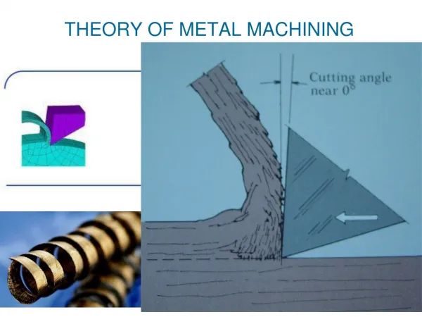
ls Orthogonal model Machining terminology (cont.) Chip thickness – thickness of machined chip (tc ) Depth of cut = to Shear plane length – measured along shear plane chip (ls ) Chip width (not shown) – width of machined chip (w) Shear angle – angle of shearing surface measured from tool direction (f)
Cutting conditions Note: - Primary cutting due to speed - Lateral motion of tool is feed - Tool penetration is depth of cut The three together form the material removal rate (MRR): MRR =v f d with units of (in/min)(in/rev)(in) = in3/min/rev (or vol/min-rev) Types of cuts: Roughing: feeds of 0.015 – 0.05 in/rev depths of 0.1 – 0.75 in Finishing: feeds of 0.005 – 0.015 in/rev depths of 0.03 – 0.075 in
Cutting geometry Obviously, the assumed failure mode is shearing of the work along the shear plane. Chip thickness ratio = r = to / tc From the shear plane geometry: r = ls sinf/[ls cos(f - a)] which can be arranged to get tan f = r cos a /[1 – r sin a]
Cutting geometry Note from the triangles in (c) that the shear strain (g) can be estimated as g = AC/BD = (DC + AD)/BD = tan(f - a) + cot f Thus, if know r and a, can determine f, and given f and a, can determine g.
Cutting forces Since R = R’ = R’’, we can get the force balance equations: F = Fc sin a + Ft cos a F = friction force; N = normal to chip force N = Fc cos a - Ft sin a Fc = cutting force; Ft = thrust force Fs = Fc cos f - Ft sin f Fs = shear force; Fn = normal to shear plane force Fn = Fc sin f + Ft cos f Forces are presented as function of Fc and Ft because these can be measured. Friction angle = b tan b = m = F/N Shear plane stress: t = Fs/As where As = to w/sin f
Cutting forces given shear strength Letting S = shear strength, we can derive the following equations for the cutting and thrust forces*: Fs = S As Fc = Fs cos ( b - a)/[cos ( f + b - a)] Ft = Fs sin ( b - a)/[cos ( f + b - a)] * The other forces can be determined from the equations on the previous slide.
Merchant equations Combining the equations from the previous slides: t = (Fc cos f - Ft sin f)/(tow/sin f )Merchant eqn The most likely shear angle will minimize the energy. Applying dt/df = 0 gives: f = 45° + a/2 - b/2 Merchant reln What does the Merchant relation indicate? The Merchant reln is a function of a and b. Where did these variables come from? Answer - Although the Merchant eqn is not shown as a direct function of a and b, these enter from the equations for Fc and Ft from the previous slide! If we increase the shear angle, we decrease the tool force and power requirements! • increase in friction angle decreases shear angle • increase in rake angle increases shear angle
Cutting models The orthogonal model for turning approximates the complex shearing process: to = feed (f) w = depth of cut (d)
Cutting power Power is force times speed: P = Fc v (ft-lb/min) The cutting horsepower is hpc = Fc v/33,000 (hp) The unit horsepower is hpu = hpc/MRR units? Due to efficiency losses (E about 90%), the gross hp is hpg = hpc/E
Cutting energy Specific energy is U = Fc v/(v tow) = Fc /(tow) (in-lb/in3) The table shown contains power and specific energy ratings for several work materials at a chip thickness of 0.01 in. For other chip thicknesses, apply the figure to get a correction factor multiply U by correction factor for thickness different than 0.01”).
Machining example In orthogonal machining the tool has rake angle 10°, chip thickness before cut is to = 0.02 in, and chip thickness after cut is tc = 0.045 in. The cutting and thrust forces are measured at Fc = 350 lb and Ft = 285 lb while at a cutting speed of 200 ft/min. Determine the machining shear strain, shear stress, and cutting horsepower. Solution (shear strain): Determine r = 0.02/0.045 = 0.444 Determine shear plane angle from tan f = r cos a /[1 – r sin a] tan f = 0.444 cos 10 /[1 – 0.444 sin 10] => f = 25.4° Now calculate shear strain from g = tan(f - a) + cot f g = tan(25.4 - 10) + cot 25.4 = 2.386 in/in answer!
Machining example (cont.) In orthogonal machining the tool has rake angle 10°, chip thickness before cut is to = 0.02 in, and chip thickness after cut is tc = 0.045 in. The cutting and thrust forces are measured at Fc = 350 lb and Ft = 285 lb while at a cutting speed of 200 ft/min. Determine the machining shear strain, shear stress, and cutting horsepower. Solution (shear stress): Determine shear force from Fs = Fc cos f - Ft sin f Fs = 350 cos 25.4 - 285 sin 25.4 = 194 lb Determine shear plane area from As = to w/sin f As = (0.02) (0.125)/sin 25.4= 0.00583 in2 The shear stress is t = 194/0.00583 = 33,276 lb/in2 answer!
Machining example (cont.) In orthogonal machining the tool has rake angle 10°, chip thickness before cut is to = 0.02 in, and chip thickness after cut is tc = 0.045 in. The cutting and thrust forces are measured at Fc = 350 lb and Ft = 285 lb while at a cutting speed of 200 ft/min. Determine the machining shear strain, shear stress, and cutting horsepower. Solution (cutting horsepower): Determine cutting hp from hpc = Fc v/33,000 hpc = (350) (200)/33,000 = 2.12 hp answer!
Cutting temperatures In machining 98% of the cutting energy is converted into heat. This energy flows into the work part, chip, and tool. Cook determined an experimental equation for predicting the temperature rise at the tool-chip interface during machining: DT = 0.4 U (v to/K)0.333/(rc) where DT = mean temperature rise (°F) U = specific energy (in-lb/in3) v = cutting speed (in/s) to = chip thickness before cut (in)rc= volumetric specific heat of the work material (in-lb/(in3-°F)) K = thermal diffusivity of the work material (in2/s) Note - To get total temperature at tool-chip interface, must add in ambient temperature! Example in text calculates DT = 936° total tool temperature, given v = 200 ft/min, rc = 120 in-lb/(in3- °F) and K = 0.125 in2/s
Cutters Toroid
Machining What did we learn?