Survivability Of SDH Network
290 likes | 458 Views
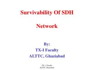
Survivability Of SDH Network. By: TX-I Faculty ALTTC, Ghaziabad. Concept of a Speech in Point to Point link. RX. TX. RX. TX. SDH Rings. 1 SDH is normally configured in a ring architect. 2 This is done to create loop diversity for uninterrupted

Survivability Of SDH Network
E N D
Presentation Transcript
Survivability Of SDHNetwork By: TX-I Faculty ALTTC, Ghaziabad TX- 1 Faculty ALTTC, Ghaziabad
Concept of a Speech in Point to Point link RX TX RX TX TX- 1 Faculty ALTTC, Ghaziabad
SDH Rings • 1 SDH is normally configured in a ring architect. • 2 This is done to create loop diversity for uninterrupted • service protection purposes in case of link failures. • 3.The SDH rings are commonly called self healing rings, • Because traffic flowing in a certain path can be switched • automatically to an alternate path. • 4.Self healing rings works on two different type of chemistry. • A- Unidirectional Self healing rings. • B- Bi-directional Self healing rings . • 5. The concept of traffic in both type ring is different. TX- 1 Faculty ALTTC, Ghaziabad
Features of SDH Rings • There can be either two or four fibers running between • the nodes on a ring. • 2. The operating signals can travel either clockwise or counter • clock only (USHR). • 3. The operating signals can travel in both directions around • The ring (BSHR). • 4.Protection switching can be performed either via a line switched • Or a path switching scheme. • 5.In BSNL only two fiber ring mechanism is being adopted. TX- 1 Faculty ALTTC, Ghaziabad
Concept of Speech in SDH Ring A – in Uni Directional Self Healing Ring RX TX TX RX ADM A ADM B TX RX RX TX TX RX RX TX ADM D RX TX TX RX ADM C TX- 1 Faculty ALTTC, Ghaziabad
Features of USHR TX- 1 Faculty ALTTC, Ghaziabad
ContinuedFeatures of USHR • The chemistry of USHR is less informative. • But it protect traffic positively. • It offers cost effective solution for low level of • capacity network. TX- 1 Faculty ALTTC, Ghaziabad
In USHR , two type of protection scheme are applicable 1- Path protection 2- line switched protection TX- 1 Faculty ALTTC, Ghaziabad
USHR – Path Protection Node A Node E Node B Node D Node C TX- 1 Faculty ALTTC, Ghaziabad
Actually in our system path protection is not there Q. Why Ans. In our systems we are keeping on auto laser set and auto laser restart functions on always. So if one fiber is going to be faulty both ends lasers switched off and it simulate the condition of complete section faulty condition. TX- 1 Faculty ALTTC, Ghaziabad
Concept of Line Switched Protection • In our systems actually line switch protections is available • It satisfied three condition • Traffic is always in Ring • And traffic always in one direction • Traffic is in ring of one fiber. TX- 1 Faculty ALTTC, Ghaziabad
Concept of Line Switched Protection A – in Uni Directional Self Healing Ring RX TX TX RX ADM A ADM B TX RX RX TX TX RX RX TX ADM D RX TX TX RX ADM C TX- 1 Faculty ALTTC, Ghaziabad
Feature of BSHR • The chemistry of BSHR is more informative. • The scheme requires a APS protocol to make operative. • The traffic flows from node 1 to node 3 in clockwise • Direction along links 1p and 2 p. • But in return path the traffic flows in counter clockwise • From node 3 to node1 along links 7p and 8p. • Thus the information exchange between nodes 1and3 does • not tie up any of the primary channel bandwidth in the other • Half of the ring. TX- 1 Faculty ALTTC, Ghaziabad
Concept of Speech in SDH Ring A – in Bio Directional Self Healing Ring RX TX TX RX Node 1 4p 1p 8p Node 2 5p TX RX RX TX TX RX RX TX Node 4 7p 6p 2p RX TX TX RX 3p Node 3 TX- 1 Faculty ALTTC, Ghaziabad
Concept of BSHR – Protection Mechanism • To understand the concept of BSHR – it is very essential to understand the concept of traffic. • Traffic is Theoretically of two type • Centralized Traffic • Distributed Traffic • But practically traffic is having mixed concept TX- 1 Faculty ALTTC, Ghaziabad
Master Station S6 S1 S1 S6 S1 RX TX TX RX S6 S1 RX TX TX RX S6 RX TX TX RX RX TX TX RX S1 0 RX TX TX RX S6 15 1 2 S6 RX TX TX RX 14 S1 S1 S6 RX TX TX RX 3 13 RX TX TX RX S6 4 S1 S1 RX TX TX RX S6 12 RX TX TX RX 5 S6 S1 RX TX TX RX 11 S1 10 RX TX TX RX S6 6 S6 7 RX TX TX RX 9 8 S1 S1 RX TX TX RX RX TX TX RX S6 S6 RX TX TX RX S1 S1 S6 S6 S1 Concept of Centralized Traffic Pattern ( Without MS-spring) TX- 1 Faculty ALTTC, Ghaziabad
Centralized Traffic Pattern 8 AU-4s Node A Node B 8 AU-4s 6 AU-4s 16 AU-4s total Spare between Nodes A & B and Nodes A & D are at capacity 6 AU-4s Two fiber STM-16 ring Two-fibre STM-16 ring Node D Node C 2 AU-4s 2 AU-4s TX- 1 Faculty ALTTC, Ghaziabad
Since all the traffic is designated • for node A, and the span Between • Node A and node B is full. • Traffic from node C routes • through node D, Leaving the • span between Node B And • node C vacant. TX- 1 Faculty ALTTC, Ghaziabad
Purely Distributed Traffic Pattern 8 AU- 4s Node A Node B 8 AU-4s 8 AU-4s 8 AU-4s 8 AU-4s 32 AU-4s total Two-fibre STM-16 ring All spare are at capacity Node D Node C 8 AU-4s 8 AU-4s TX- 1 Faculty ALTTC, Ghaziabad
Mixed Traffic Pattern 3 AU-4s 3 AU-4s 3 AU_4s 3 AU-4s 2 AU-4s Node A Node B 2 AU-4s 8 AU-4s 5 AU-4s 1 AU-4s 22 AU-4s total Two-fibre STM-16 ring All spare are at capacity Node D Node C 4 AU-4s 4 AU-4s T1516760-94d11 4 AU-4s 4 AU-4s TX- 1 Faculty ALTTC, Ghaziabad
MS shared protection rings • MS shared protection rings scheme is supported by only BSHR • .The ring protocol is essential for both two fiber ring or four • Fiber ring. • In BSNL only two fiber rings are deployed. • MS shared protection rings are characterized by dividing • the total payload per multiplex section equally into working • and protection capacity. • For a two fiber STM_N ring, N/2 administrative unit • Groups (AUGs) available for working and N/2 (AUGs) • for protection. • The protection capacity is shared between multiple • Multiplex sections TX- 1 Faculty ALTTC, Ghaziabad
The sharing of protection capacity may allow a multiplex • section shared protection ring to carry more traffic under • Normal conditions than other ring types. • The sum of the tributaries that transverse a span cannot • exceed the maximum capacity of the particular span. • In MS shared protection the service can be routed in either • one of the two directions,the long way around the ring or the • short way. • For normal working shortest path is preferable. • For failure condition ,the alternate path in used. TX- 1 Faculty ALTTC, Ghaziabad
Normal Traffic In MS-Spring Node a Node b Node c Node C Node A Node B Circuit Q Node f Node e Node D Node F Node E Node d working Working Normal state protection Protection Ckt transporting service TX- 1 Faculty ALTTC, Ghaziabad Circuit Transporting Service
Protected Traffic In MS-Spring Node a Node c Node C Node A Node B Node b Circuit Q ` Node f Node D Node F Node E Node e working Node d Working protection Failed state Protection Ckt transporting service TX- 1 Faculty ALTTC, Ghaziabad Circuit Transporting Service
Procedure of loading MS-spring. • Prepare physical map of ring of different nodes. • assign individual node ID to each node either in clockwise direction or in counter clockwise direction . • Zero node ID be offered to master node. • Maximum station may not be more than 16 excluding regenerator. TX- 1 Faculty ALTTC, Ghaziabad
Master Station S6 S1 S1 S6 S1 RX TX TX RX S6 S1 RX TX TX RX S6 RX TX TX RX RX TX TX RX S1 0 RX TX TX RX S6 15 1 2 S6 RX TX TX RX 14 S1 S1 S6 RX TX TX RX 3 13 RX TX TX RX S6 4 S1 S1 RX TX TX RX S6 12 RX TX TX RX 5 S6 S1 RX TX TX RX 11 S1 10 RX TX TX RX S6 6 S6 7 RX TX TX RX 9 8 S1 S1 RX TX TX RX RX TX TX RX S6 S6 RX TX TX RX S1 S1 S6 S6 S1 Procedure of loading MS-spring. TX- 1 Faculty ALTTC, Ghaziabad
Translate physical map of STM – 16 Ring in to soft copy • Follow the screen instruction for further loading the rings. TX- 1 Faculty ALTTC, Ghaziabad
Preparation of MS – Spring Node Map Editor TX- 1 Faculty ALTTC, Ghaziabad