
SE207 Modeling and Simulation
E N D
Presentation Transcript
SE207 Modeling and Simulation Lab # 3: Analog Simulation of a First Order System (RC circuit)
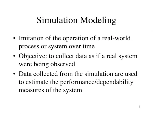
Objectives • The objective of this experiment is to simulate a first order system (an RC circuit) and study its behavior.
Equipment • GP-6 Analog Computer • X-Y plotter
First Order Systems • First order systems are modeled by first order Differential equations. • Any circuit containing a resistor and a capacitor can be modeled by a first order model.
RC Circuit The RC circuit is modeled by the equation. + _ R C Vc (t)
Time constant of a First Order System • The final value of Vc(t) =E • The time at which Vc(t)=0.63 * final value is called the time constant of the system. Vc(t) Final value of Vc(t) 63% of Final value of Vc(t) t Time constant
Time constant • Time constant depends on C and R • Larger time constant means the capacitor needs longer time to charge.
Drawing Simulation DiagramsFirst order Example 0.5x(t) -0.25 x(t)
Drawing Simulation DiagramsFirst order Example (cont.) 0.5 0.5x(t) -0.25 1 1 x(t) 0.25 -1.0
Procedure • Write the system of equation in a form suitable for drawing analog simulation diagram • Draw the analog simulation diagram corresponding to the value given in the table. Assume E(t) = 1.0 Volt and Vc(0)=0
Procedure (cont.) • For the first set of values, connect the analog computer circuit on the GP-6 using one integrator. • Set the Y/Pot-address to GND/X and mode selector to OPR. • Select the output amplifier from the X-address, press OP button and monitor the output of the system Vc(t) • Repeat step (4) and plot the output on the X-Y plotter • Repeat steps (1- to 5) for the second set of values of R and C.
Report Your report should include the following • A plot of the output voltage for the two cases • Estimates of the system’s time constants in both cases • Comparison of the theoretical and experimental values of the time constants in both cases • Comments and conclusions on your observations