Download
1 / 18
180 likes | 197 Views
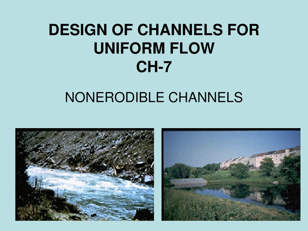
Explore the factors and materials involved in designing nonerodible channels. Learn about velocities, slopes, and the best hydraulic section. Find out how to determine proper section dimensions and freeboard requirements for optimal channel performance.

E N D
DESIGN OF CHANNELS FOR UNIFORM FLOWCH-7 NONERODIBLE CHANNELS
The Nonerodible Channel • Most lined channels and built-up channels can withstand erosion satisfactorily and are therefore considered nonerodible. • Unlined channels are generally erodible, except those excavated in firm foundations, such as rock bed
The Nonerodible Channel • The factors to be considered in the design: • The kind of material forming the channel body • The roughness coefficient • The minimum permissible velocity • The channel bottom slope • Side slopes • The freeboard • The most efficient section, either hydraulically or empirically determined.
Nonerodible Material and Lining • The nonerodible materials used to form the lining of a channel and the body of a built-up channel include concrete, stone masonry, steel, cast iron, timber, glass, plastic, etc. • The nonerodible materials used to form the lining of a channel and the body of a built-up channel include concrete, stone masonry, steel, cast iron, timber, glass, plastic, etc.
The Minimum Permissible Velocity • The minimum permissible velocity, or the nonsilting velocity, is the lowest velocity that will not start sedimentation and induce the growth of aquatic plant and moss. • Generally speaking, a mean velocity of 2 to 3 fps may be used safely • A mean velocity of not less than 2.5 fps will prevent a growth of vegetation that would seriously decrease the carrying capacity of the channel.
Channel Slopes • The longitudinal bottom slope of a channel is generally governed by the topography and the energy head required for the flow of water
Channel Slopes • Other factors to be considered in determining slopes are method of construction, condition of seepage loss, climatic change, channel size, etc. • For lined canals, the U.S. Bureau of Reclamation has been considering standardizing on a 1.5:1 slope for the usual sizes of canals.
Free board • The freeboard of a channel is the vertical distance from the top of the channel to the water surface at the design condition. • Freeboards varying from less than 5 % to greater than 30 % of the depth of flow are commonly used in design
Free board • For lined canals or laterals, the height of lining above the water surface will depend upon a number of factors: • size of canal, • velocity of water, • curvature of alignment, • condition of storm- and drain-water inflow, • fluctuations in water level due to operation of flow-regulating structures, • wind action.
The Best Hydraulic Section • It is known that the conveyance of a channel section increases with increase in the hydraulic radius or with decrease in the wetted perimeter.
Determination or section dimensions • Follow the steps: • Collect all necessary information, estimate n, and select S. • Compute the section factor AR2/3 • Solve for the water depth from finding A and R. • For lined channel used Fig. 7-2
Determination or section dimensions • Follow the steps: • If the best hydraulic section is required directly, substitute in Eq. (6-8) the expressions for A and R obtained from Table 7-2 and solve for the depth. • For the design of irrigation channels, the channel section is sometimes proportioned by empirical rules such as the simple rule given by the early U.S. Reclamation Service for the full supply depth of water in feet:
Determination or section dimensions • Follow the steps: • Check the minimum permissible velocity if the water carries silt. • Add a proper freeboard to the depth of the channel section.